
Auger for snow throw machine

a technology for snow throwers and augers, applied in snow cleaning, way cleaning, construction, etc., can solve the problems of limited damage to individual flytes and not to the auger transmission or engin

Inactive Publication Date: 2007-12-11
MTD PRODUCTS
View PDF23 Cites 29 Cited by
  • Summary
  • Abstract
  • Description
  • Claims
  • Application Information

AI Technical Summary

Benefits of technology

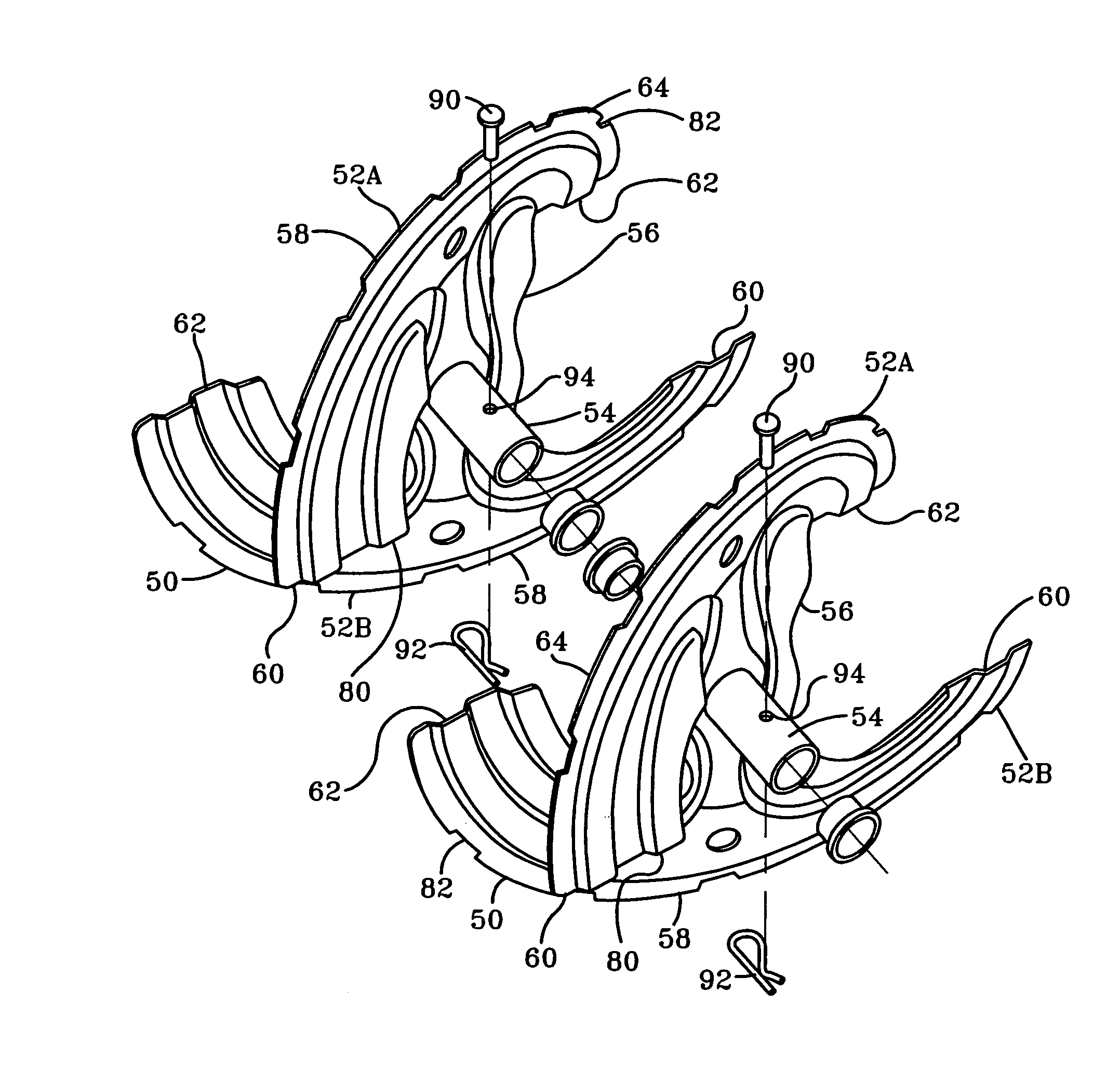
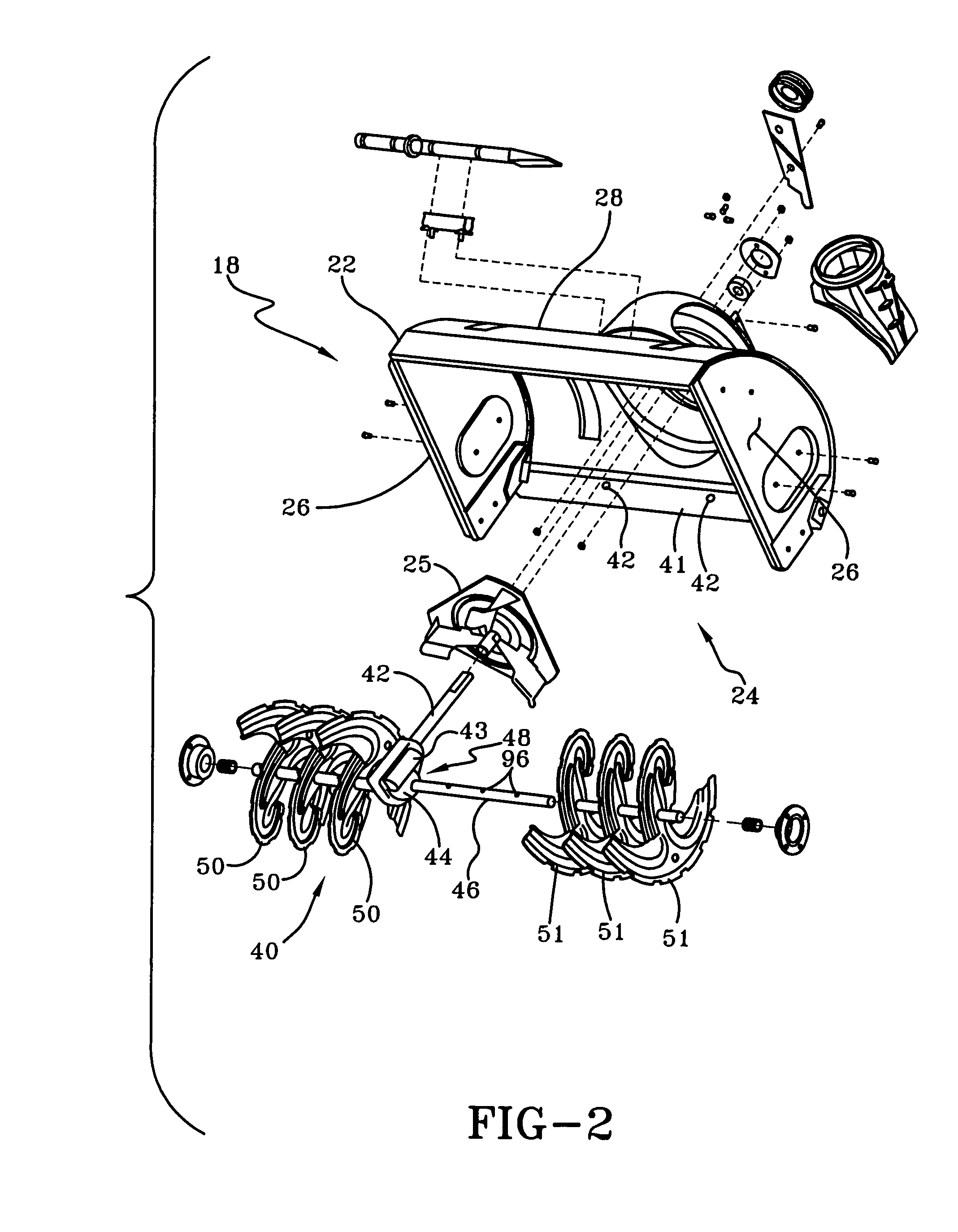
The present invention provides an auger for a snow thrower that is made of a plurality of individually stamped blades or flytes. The flytes are mounted on the auger shaft using a shearing member, and can be easily replaced if damaged without having to replace the entire auger. The flytes are mounted on the auger shaft such that damage can be limited to the individual flytes and not to the auger transmission or engine. The snow thrower includes an auger for collecting snow and directing it to the impeller, and the auger is made of stainless steel. The snow throwing machine also includes a scraping blade made of stainless steel to push any snow the auger does not capture located at the bottom of the housing. The technical effects of this invention include improved durability and corrosion resistance of the auger, as well as easier replacement of damaged flytes.

Problems solved by technology

Furthermore, the individual flytes are mounted on the auger shaft such that damage can be limited to the individual flytes and not to the auger transmission or engine.

Method used


Image

  • Auger for snow throw machine
  • Auger for snow throw machine
  • Auger for snow throw machine

Examples


Embodiment Construction

[0020]The invention will now be described in the following detailed description with reference to the drawings, wherein preferred embodiments are described in detail to enable practice of the invention. Although the invention is described with reference to these specific preferred embodiments, it will be understood that the invention is not limited to these preferred embodiments. But to the contrary, the invention includes numerous alternatives, modifications and equivalents as will become apparent from consideration of the following detailed description.

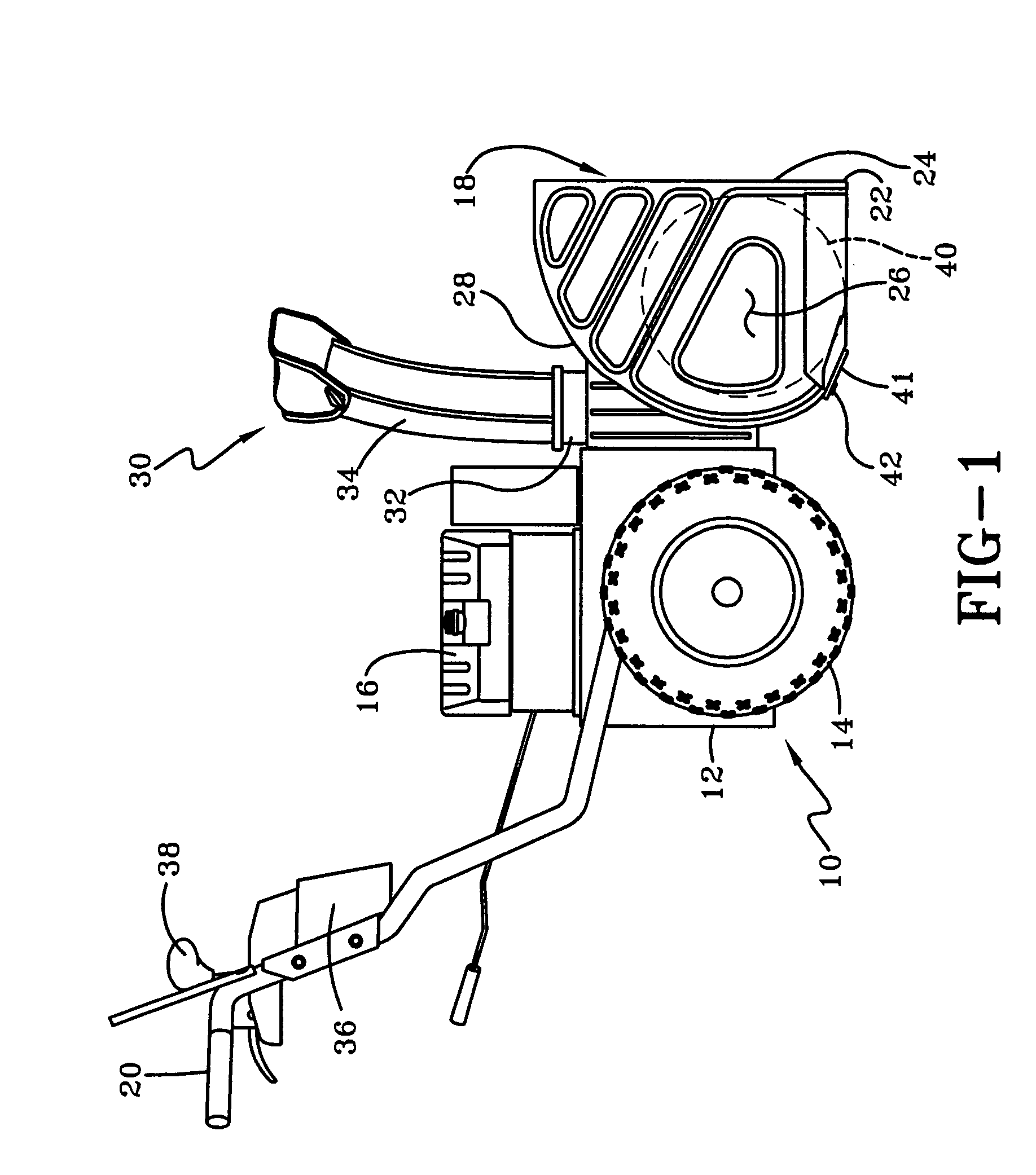
[0021]Referring now to FIG. 1, a walk-behind snow throwing machine is shown generally at 10. The snow thrower 10 includes a frame 12 and ground-engaging wheels 14, operatively coupled to the frame. A power source 16, such as an internal combustion engine or other suitable power source, is fixedly attached to the frame 12 and provides power for operating a snow-gathering unit, indicated generally 18, attached to the front end of the ...


PUM


Abstract

A snow throwing machine including a housing, an engine, an impeller and an auger for collecting snow and directing it to the impeller. The auger including an auger shaft disposed transversely in the housing and drivable by the engine, and a plurality of flytes mounted on the auger shaft. Each flyte includes a hub and a plurality of fins and is mounted on the auger shaft with a shear pin extending through the hub and auger shaft. The flytes are configured such that an outer peripheral edge of adjacent flytes forms a helix around the auger shaft directing snow toward the impeller.

Description

[0001]This application claims priority from U.S. Provisional Application Ser. No. 60 / 566,475, filed Apr. 29, 2004, and entitled AUGER FOR SNOW THROWING MACHINE.BACKGROUND OF THE INVENTION[0002]1. Field of Invention[0003]This invention relates a snow throwing machine, and more particularly, to a snow throwing machine having an auger formed from a plurality of individually stamped flytes.[0004]2. Description of Related Art[0005]Snow throwers designed to remove snow from sidewalks, driveways and roadways after a snowstorm are well known in the art. Snow throwers can be mounted to a motor vehicle such as a tractor or can be walk-behind models that are self-propelled or manually pushed by the operator. Conventional snow throwers are usually classified as having either a single stage or two stage snow propelling design. Snow throwers typically have a housing with a front opening through which snow is taken in between spaced apart sidewalls and a snow chute and snow deflector through which...

Claims


Application Information

Patent Timeline
Patent Type & Authority Patents(United States)
IPC IPC(8): E01H5/04E01H5/09
CPCE01H5/098E01H5/04
Inventor KETTERING, TRAVISPULLUM, ROY G.
Owner MTD PRODUCTS
Learn More