Ported tri-hull boat

a tri-hull boat and port technology, applied in special-purpose vessels, vessel construction, transportation and packaging, etc., can solve the problems of affecting the use of the boat, and not having a smooth rid

Active Publication Date: 2007-12-11
SEIDER DENNIS J
View PDF13 Cites 11 Cited by
  • Summary
  • Abstract
  • Description
  • Claims
  • Application Information

AI Technical Summary

Benefits of technology

[0006]Accordingly, it is an object of the present invention to provide a scalable fast, wave / surface piercing tri-hull vessel offering the strength of a monohull, the ride of a hydrofoil, the stability of a tri-hull and the ability to combine the advantages of all three types of hulls at high speed and in a variety of sea states.
[0007]It is a further object of the present invention to provide a tri-hull design which allows the vessel to rise partially out of the water generally isolating the vessel from the surface and that will run efficiently at high speed with minimum wetted surface.
[0008]It is a still further object of the present invention to provide a tri-hull design allowing the vessel to come down at great speed on the surface of the water without bottoming out by pushing the water to the side, rather than trapping the water against the outside sponsons as in a conventional tri-hull which otherwise has its downward momentum stopped abruptly by the trapped water, often causing a jarring impact and loss of speed.

Problems solved by technology

Displacement vessels move through the water comfortably but slowly, while planing vessels rise and ride on top of the water when power is applied but the ride can be jarring as the boat contacts the surface of the water.
Monohull vee-bottom boats are strong and can displace water to the sides but do not have the smooth ride of a surface piercing design and are slowed by the amount of wetted surface.
Multi-hull designs are also popular with the surface piercing and wider stance offering greater comfort and stability but are of limited use in rough water because of the tendency to.
Tunnel boats are designed to trap a cushion of air beneath the hull to reduce drag but also suffer in rough water and can bottom out.
Other boats have been designed to ride on foils or skis, typically attached to the vessel by struts which are subject to damage from impact or mechanical failure.

Method used


Image

  • Ported tri-hull boat
  • Ported tri-hull boat
  • Ported tri-hull boat

Examples


Embodiment Construction

[0022]

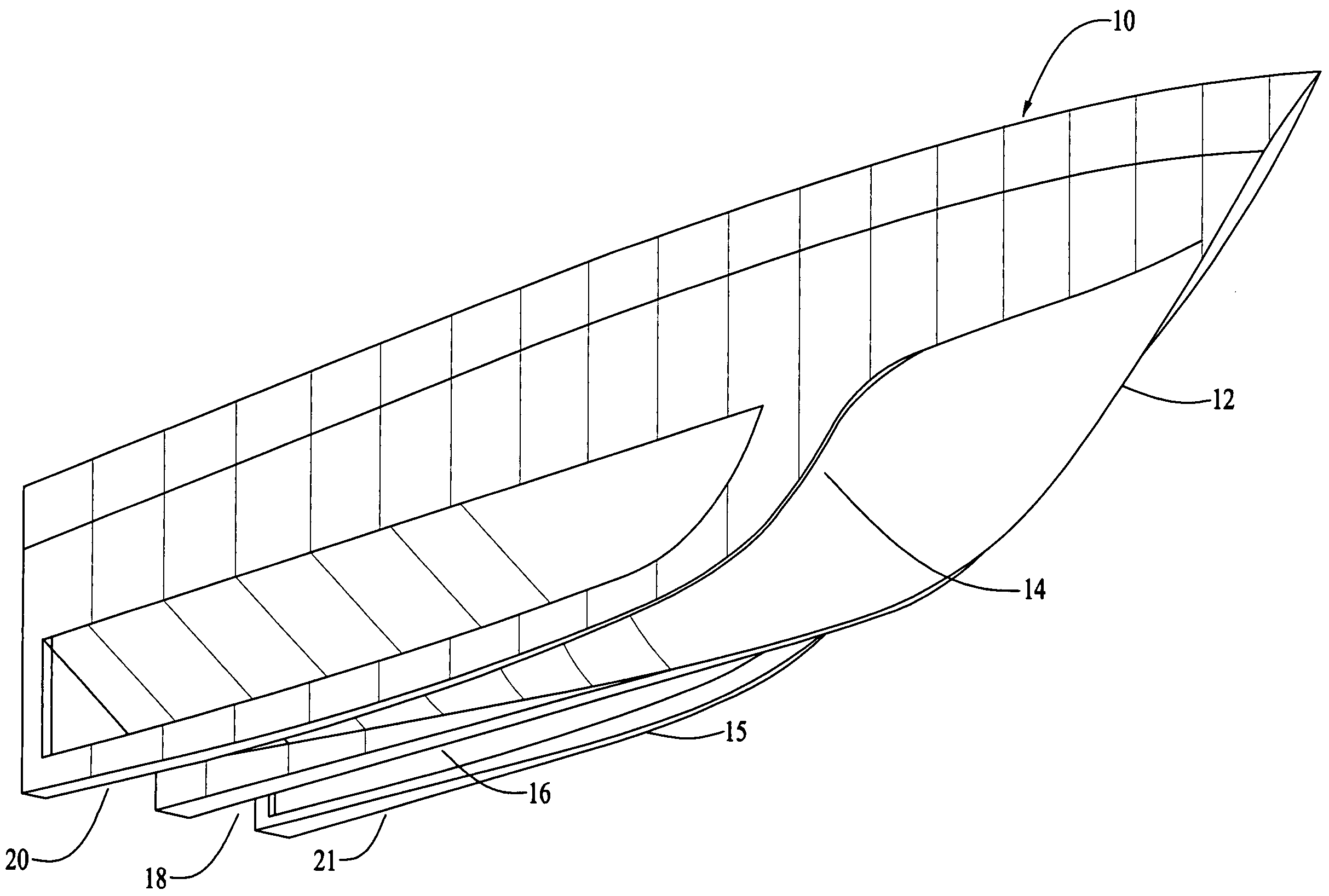
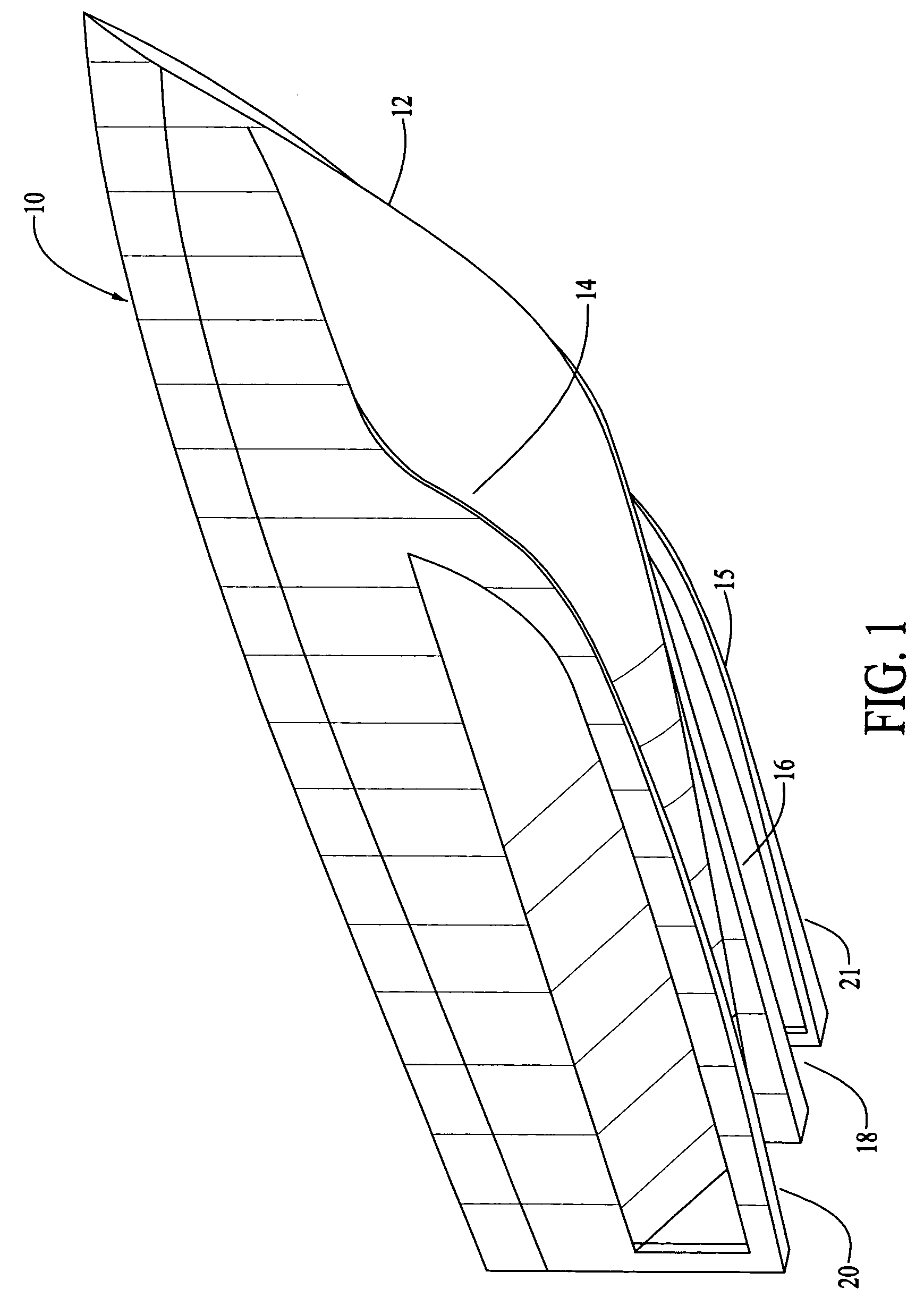
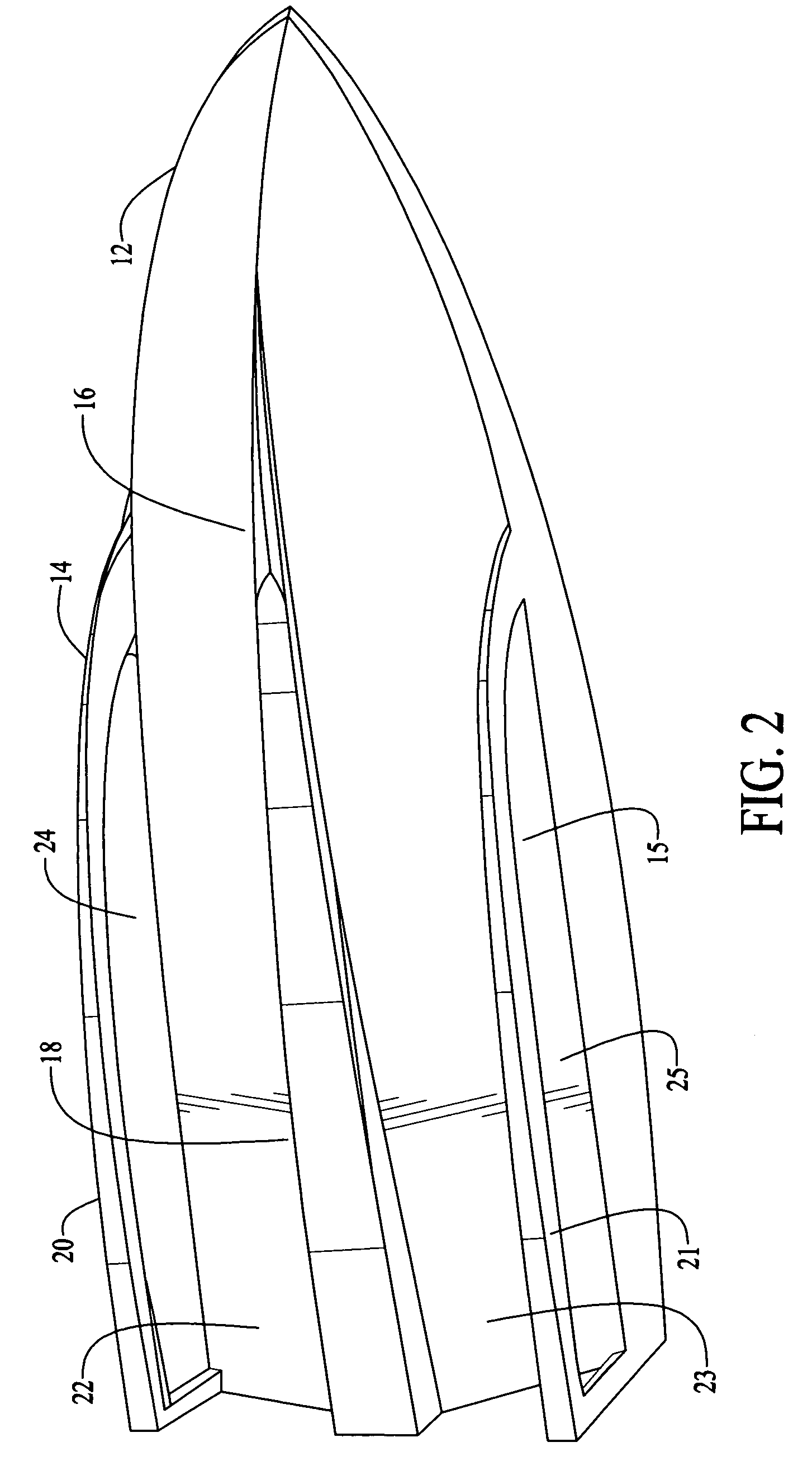
tri-hull boat10center hull12opposing pair of sponsons or skis14, 15.keel16center planing surface18outboard planing surfaces20, 21aft center hull structure22, 23sponson openings or ports24, 25planeP

DESCRIPTION OF THE PREFERRED EMBODIMENT(S)

[0023]Referring to FIGS. 1-6 the preferred embodiment of the present invention may be described. First referring primarily to FIGS. 1-4, shown is a tri-hull boat 10 includes a vessel having a generally vee-shaped center hull 12 with an opposing pair of sponsons or skis 14, 15. The center hull 12 at the chine has a keel 16 that runs longitudinally from the bow to the stern portions of the boat, and flattens out and substantially widens as it extends aft to form a center planing surface 18. Similarly the sponsons 14, 15 are vee shaped at the bow and flatten and widen towards the stern forming outboard planing surfaces 20, 21, all those planning surfaces 20, 21 and the central planning surface 18 being in approximately the same plane P. The dead...


PUM


Abstract

A boat for traveling at speed across a body of water includes a center hull having a vee-shaped bottom with a center planing surface, and an opposing pair of sponsons or ski-like structures attached outboard of the center and extending substantially alongside the central hull. Importantly, the sponsons or skis each have a substantial opening such that large volumes of water are able to pass through in an outboard direction away from the boat, advantageously minimizing forces on the hull when there is substantial vertical downward movement of the boat. The boat is designed so that planing surfaces of the keel and sponsons operate beneath the surface of the water to lift the hull free and isolate it from the rough water surface.

Description

CROSS REFERENCE TO RELATED DOCUMENTS[0001]This application is based on provisional patent application Ser. No. 60 / 689,429 filed Jun. 10, 2005, the contents of which are incorporated by reference.BACKGROUND OF THE INVENTION[0002]1. Field of the Invention[0003]The present invention relates generally to watercraft designs and more particularly to a tri-hull power boat having specially-designed sponsons for top performance and a comfortable ride.[0004]2. Description of the Related Art[0005]Boat designs vary considerably depending upon the specific use for which the boat is planned. Displacement vessels move through the water comfortably but slowly, while planing vessels rise and ride on top of the water when power is applied but the ride can be jarring as the boat contacts the surface of the water. Monohull vee-bottom boats are strong and can displace water to the sides but do not have the smooth ride of a surface piercing design and are slowed by the amount of wetted surface. Multi-hul...

Claims


Application Information

Patent Timeline
Patent Type & Authority Patents(United States)
IPC IPC(8): B63B1/00
CPCB63B1/042B63B2001/186B63B2001/201B63B2001/005
Inventor SEIDER, DENNIS J.
Owner SEIDER DENNIS J
Why Eureka
Try Eureka