Low crosstalk transmission connector

Inactive Publication Date: 2007-12-11
TELEBOX INDS CORP
View PDF6 Cites 11 Cited by
  • Summary
  • Abstract
  • Description
  • Claims
  • Application Information

AI Technical Summary

Benefits of technology

[0003]The present invention has been accomplished under the circumstances in view. According to one aspect of the present invention, the low crosstalk transmission connector is comprised of an electrically insulative housing, a metal spring plate, a load bar, a terminal module, a locating frame, a cable organizer, and a metal shield. After the housing has been assembled with the metal spring plate, the load bar, the terminal module and the locating frame, the cable is inserted the metal shield and the cable organizer with the 8 insulated wires respectively set in respective wire grooves in the cable organizer, and then a bottom clamping plate of the metal shield is h

Problems solved by technology

Further, the installation of the parts of the transmission connector 92 is complicated.
Further, the transmi

Method used


Image

  • Low crosstalk transmission connector
  • Low crosstalk transmission connector
  • Low crosstalk transmission connector

Examples


Example

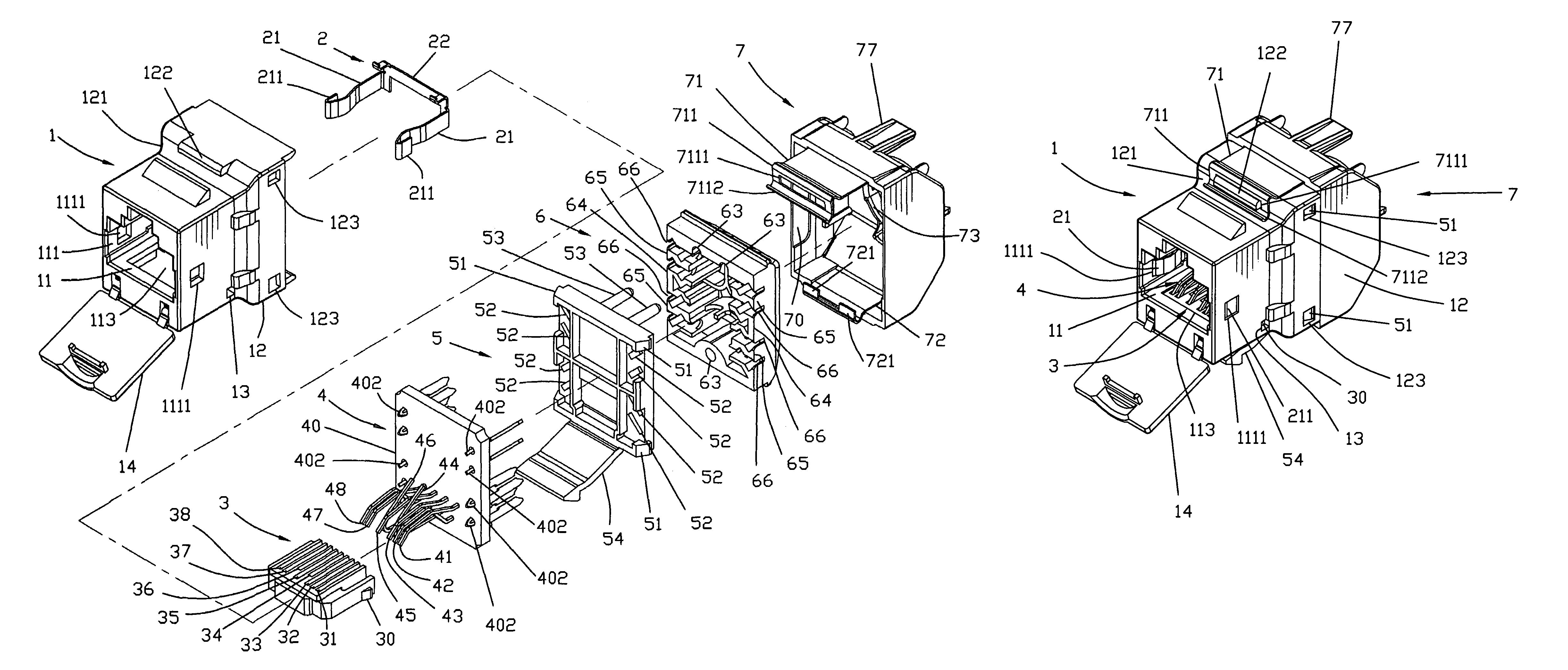
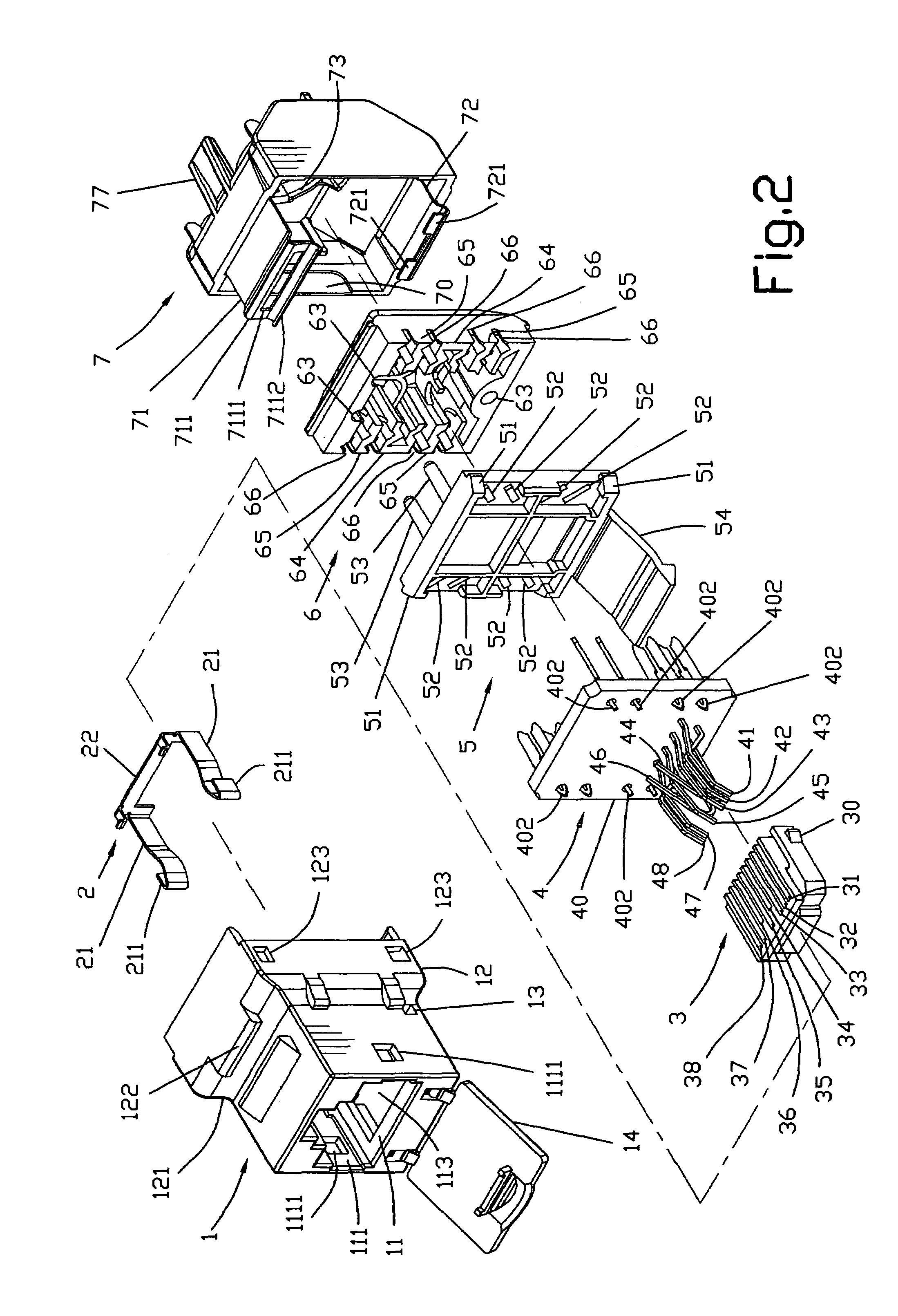
[0027]Referring to FIGS. 2˜22, a low crosstalk transmission connector in accordance with the present invention is shown comprised of an electrically insulative housing 1, a metal spring plate 2, a load bar 3, a terminal module 4, a locating frame 5, a cable organizer 6, and a metal shield 7.

[0028]The housing 1 has in its rectangular front part a forwardly extending front insertion hole 11, two locating grooves 111 at the two opposite lateral sides of the insertion hole 11, two locating holes 1111 respectively cut through the two opposite lateral sidewalls of the rectangular front part in communication with the locating grooves 111, two stop blocks 112 bilaterally disposed inside the front insertion hole 11 (see FIGS. 5 and 9), and a positioning groove 113 in the bottom side inside the front insertion hole 11. The housing 1 further has a relatively greater rear part 12, a retaining groove 121 transversely extending at the top side of the rear part 12, a hook 122 suspending above the ...


PUM


Abstract

A low crosstalk transmission connector includes a housing that houses a metal spring plate, a load bar, a terminal module and a locating frame, a cable organizer, which has an axle hole that receives a 8-wire cable and 8 wire grooves that separate the 8 insulated wires of the cable, and a metal shield that accommodates the cable organizer and has a bottom clamping plate and a top clamping plate respectively hooked on the bottom and top sides of the housing to ensure high steadity. The 4th and 6th metal contact terminals and the 1st, 2nd, 3rd, 5th, 7th and 8th metal contact terminals of the terminal module have the respective front contact portions curved in two reversed directions to reduce crosstalk noise, thereby improving transmission quality.

Description

BACKGROUND AND SUMMARY OF THE INVENTION[0001]The present invention relates to electric transmission connectors and more particularly, to a low crosstalk transmission connector, which gets high steadity and, which reduces crosstalk noise to improve signal transmission quality by means of reversing the front contact portions of the 4th and 6th metal contact terminals.[0002]FIG. 1 illustrates a transmission connector 92 according to the prior art. According to this design, the transmission connector 92 is comprised of a housing 921, a circuit board 922, a load bar 923, and a cable organizer 924. The load bar 923 and the cable organizer 924 are fixedly mounted on the top side of the circuit board 922. The circuit board 922 has protruding engagement blocks 9221 respectively engaged into respective locating holes 9211 on the housing 921. The load bar 923 carries 8 metal contact terminals 9231˜9238. The metal contact terminals 9231, 9232, 9233, 9234, 9235, 9236, 9237,9238 each have a front...

Claims


Application Information

Patent Timeline
IPC IPC(8): H01R13/648
CPCH01R13/6461H01R13/6593H01R13/6474H01R24/64
Inventor CHANG, RAY
Owner TELEBOX INDS CORP
Why Eureka
Try Eureka