
Electric wire excessive length absorption device

a technology of absorption device and wire harness, which is applied in the direction of insulated conductors, cables, relatively moving parts, etc., can solve the problems of excessive length, damage, and catching between the vehicle body and the door, so as to reduce the protruding height of the harness guide outward from the case, increase the installation space of other components, and reduce the protruding height of the harness guid

Active Publication Date: 2007-12-11
YAZAKI CORP
View PDF7 Cites 7 Cited by
  • Summary
  • Abstract
  • Description
  • Claims
  • Application Information

AI Technical Summary

Benefits of technology

The present invention provides a wire harness excessive length absorbing device that is slim and allows for smooth movement of the wire harness. The device includes a case for receiving the wire harness, an urging member for pulling the wire harness out of the case, and a harness roller on which the wire harness is rolled and reciprocally moved. A harness guide is mounted on the outlet and curved towards the inlet for guiding the wire harness to the outside of the case. The wire harness is pulled out of the case or into the case depending on the movement of the door or other components. The device prevents damage to the wire harness and provides a large installation space for other components.

Problems solved by technology

Therefore, when the door is closed, an excessive length is generated in the wire harness and may be caught between the vehicle body and the door and damaged.

Method used


Image

  • Electric wire excessive length absorption device
  • Electric wire excessive length absorption device
  • Electric wire excessive length absorption device

Examples


Embodiment Construction

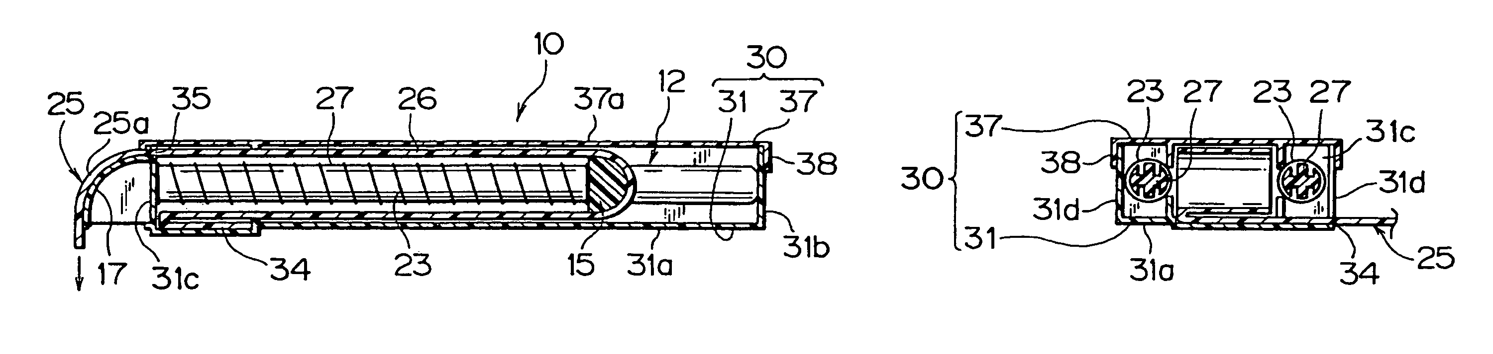
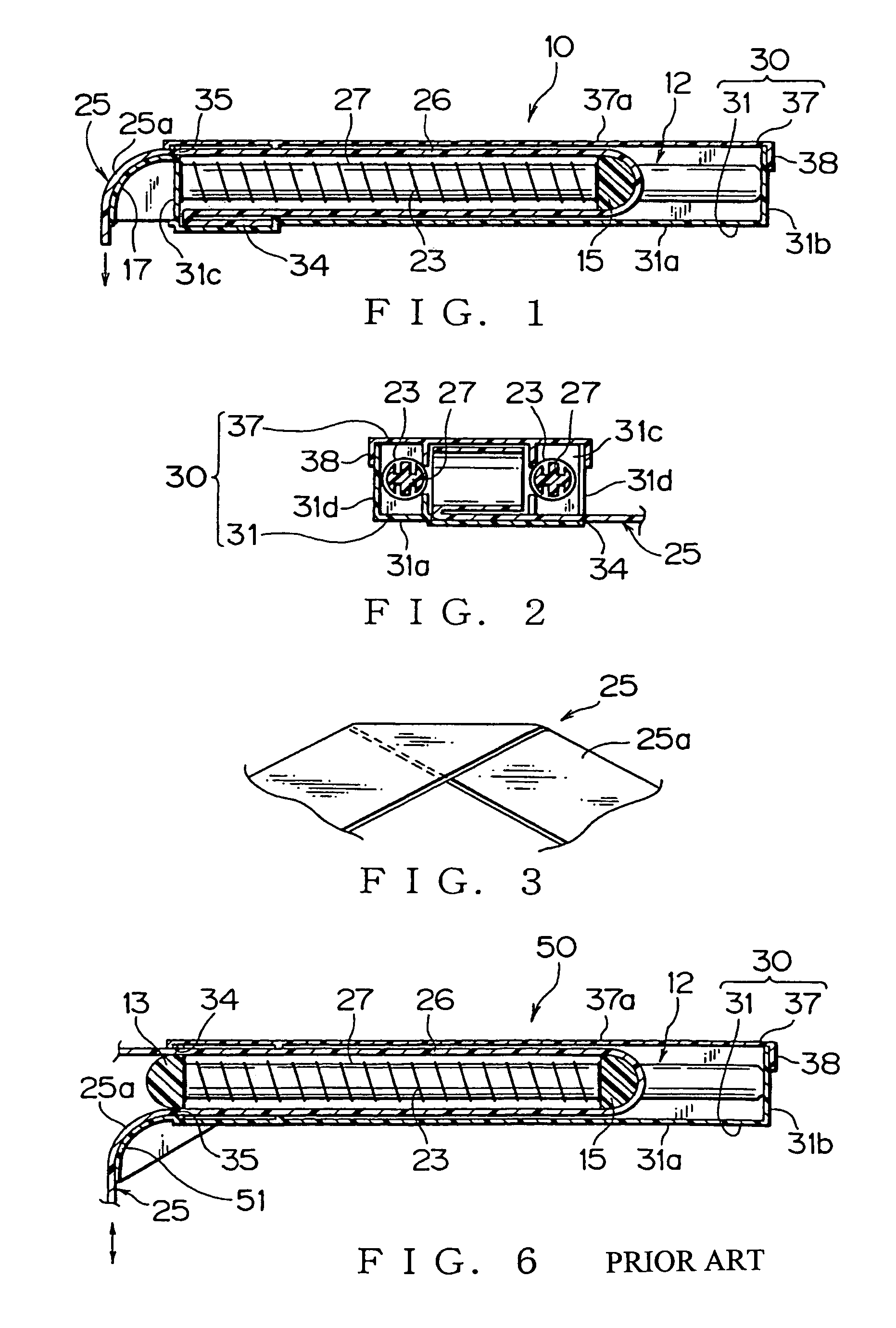
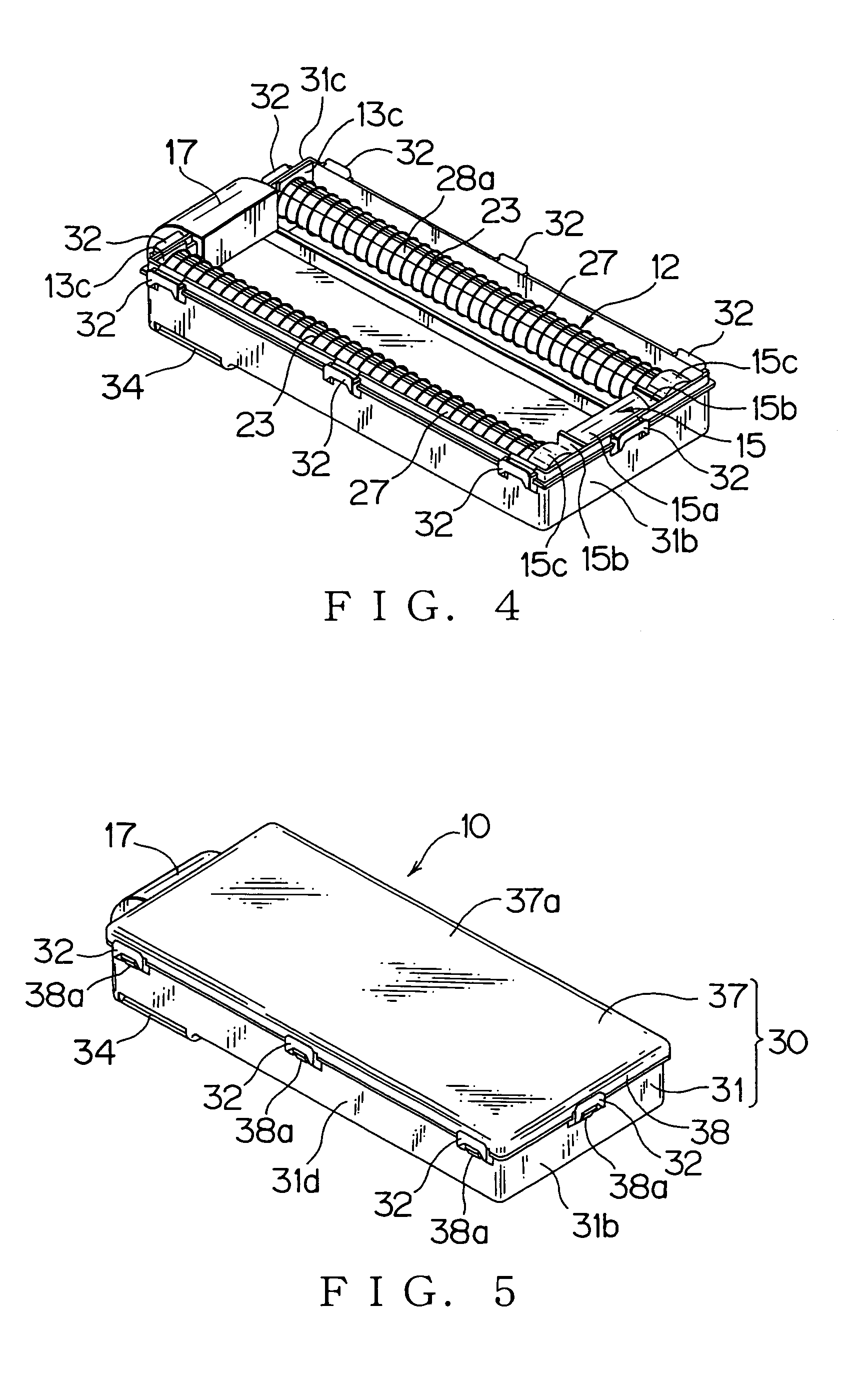
[0051]Hereunder, an embodiment of the present invention will be explained with reference to figures. FIGS. 1 to 5 show a wire harness excessive length absorbing device 10 according to the embodiment of the present invention. In order to avoid repetitions, identical elements will be designated by identical reference numerals and only the differences existing in comparison with the embodiment of the conventional wire harness excessive length absorbing device 50 will be explained.

[0052]The wire harness excessive length absorbing device 10 absorbs an excessive length (slack) 26 of a wire harness 25 interposed between a vehicle body as a fixing object (not shown) and a door as a movable object (not shown). Here, a scope of the door includes a rotary door or sliding door. The movable object is not limited to the door. For example, a trunk or a hatch may be used as the movable object.

[0053]As shown in FIG. 1, the wire harness excessive length absorbing device 10 includes the wire harness 2...


PUM

PropertyMeasurementUnit
lengthaaaaaaaaaa
thicknessaaaaaaaaaa
flexibleaaaaaaaaaa

Abstract

There is provided a wire harness excessive length absorbing device that allows a slim case body thereof, and provides a large installation space for other components. The wire harness excessive length absorbing device includes a case (30) for receiving a wire harness (25) having an inlet (34) and an outlet (35) for the wire harness (25); an urging member (23) for urging the wire harness (25) toward an inside of the case (30); and a harness roller (15) on which the wire harness (25) being rolled, said harness roller (15) reciprocally moving under acting forth of the urging member (23), a harness guide (17) mounted on the outlet (35) and curved toward the inlet (34) for guiding the harness (25) to the outside of the case (30). The harness guide (17) is curved in the same direction as a direction of the wire harness being rolled (25) on the harness roller (15). The outlet (35) is disposed in a direction perpendicular to that of the inlet (34).

Description

TECHNICAL FIELD[0001]This invention relates to a device for absorbing an excessive length of a wire harness interposed between a vehicle body as a fixed object to which the wire harness is fixed, and an openable and closable door as a sliding object mounted on the vehicle body.BACKGROUND ART[0002]As is generally known, various electric components are installed in a vehicle or the like. Power and signal currents are supplied to these electric components through a wire harness.[0003]The wire harness is a tube that ties a plurality of electric wires. Various wire harnesses are used corresponding to applications or locations. For example, a flexible flat cable in which a plurality of wiring conductors are arranged in parallel is used for connecting electric components in a vehicle door on which a power window motor, a door lock unit, a switch unit, an automatic door open / close unit and the like are installed.[0004]Travel distance of the wire harness for the door or the like is large due...

Claims


Application Information

Patent Timeline
Patent Type & Authority Patents(United States)
IPC IPC(8): H01B7/00H02G11/00H02G3/38
CPCH02G11/006H02G11/00
Inventor TERADA, TOMOYASU
Owner YAZAKI CORP
Learn More