External resonator and semiconductor laser module using the same

a technology of external resonators and laser modules, applied in semiconductor lasers, instruments, cladded optical fibres, etc., can solve the problems of changing the oscillation wavelength of laser light, side lobes having a number of peaks, and the 11b spectrum property cannot be completely removed, so as to reduce the number of parts and the effect of mounting spa

Inactive Publication Date: 2005-10-06
KYOCERA CORP
View PDF10 Cites 15 Cited by
  • Summary
  • Abstract
  • Description
  • Claims
  • Application Information

AI Technical Summary

Benefits of technology

[0009] In the process for forming FBG, a design technique referred to as apodization can be used, in which the strength distribution of irradiated UV light is controlled to be in the Gaussian state, thus making a distribution of the refractive index. This technique allows the refractive index of the phase gratings 33 that form the FBG 1 to be provided with a distribution as shown in FIG. 11A, and thus, the Fabry-Perot resonation can be suppressed.
[0014]FIG. 16 shows a structure of an inline type optical isolator. An inline type optical module 18 shown in FIG. 16 transmits light 19, which has been emitted from the semiconductor laser module 13, but removes unnecessary light 22 such as reflected returning light. However, an inline type optical isolator 6, which is expensive, is separately prepared before being mounted, and therefore, the number of parts increases, requiring a large mounting space.
[0015] In order to solve the above described problem, the present invention provides an external resonator comprising an optical fiber having a core and a cladding, said core being formed with a fiber Bragg grating that reflects light of a specific wavelength; and a ferrule that holds said optical fiber, wherein at least part of phase gratings in said fiber Bragg grating are inclined against an orthogonal plane of an optical axis of said optical fiber. As respective phase gratings within a FBG are inclined against an orthogonal plane of the optical axis of the optical fiber, an interference between reflected light and incident light are suppressed, and the Fabry-Perot resonance on both ends can be decreased as well. Therefore, side lobes and branched peaks are suppressed and, thereby, steep spectrum properties can be obtained.
[0017] Furthermore, it is preferable to provide a metal thin film around the external periphery of the cladding of the fiber. In the case where a metal thin film is deposited around the external periphery of the cladding, light that has entered the cladding can be prevented from propagating in the cladding mode and coupling to light propagating through the core. Accordingly, the output of the reflected diffraction light can stabilize.
[0019] Furthermore, in the case where an optical element such as an optical isolator is attached to an end surface of the ferrule, unnecessary light in the vicinity of the oscillation wavelength of the semiconductor laser is removed and, thus, the semiconductor laser can stably oscillate. The attached optical element preferably has an optical isolator function and an optical filtering function so as to eliminate the need of separately mounting optical modules having such functions and to reduce the number of parts and a mounting space. The optical element may have only the optical filtering function.

Problems solved by technology

This results in a change of the oscillation wavelength of laser light.
However, side lobes having a number of peaks as shown in FIG. 11B in the spectrum properties cannot be completely removed.
Accordingly, the spectrum properties of the reflection wavelength may change and, thereby, the oscillation wavelength of the semiconductor laser module 13 fluctuates, making the properties of module unstable.
However, an inline type optical isolator 6, which is expensive, is separately prepared before being mounted, and therefore, the number of parts increases, requiring a large mounting space.
Furthermore, in the case where an optical element such as an optical isolator is attached to an end surface of the ferrule, unnecessary light in the vicinity of the oscillation wavelength of the semiconductor laser is removed and, thus, the semiconductor laser can stably oscillate.

Method used


Image

  • External resonator and semiconductor laser module using the same
  • External resonator and semiconductor laser module using the same
  • External resonator and semiconductor laser module using the same

Examples


examples

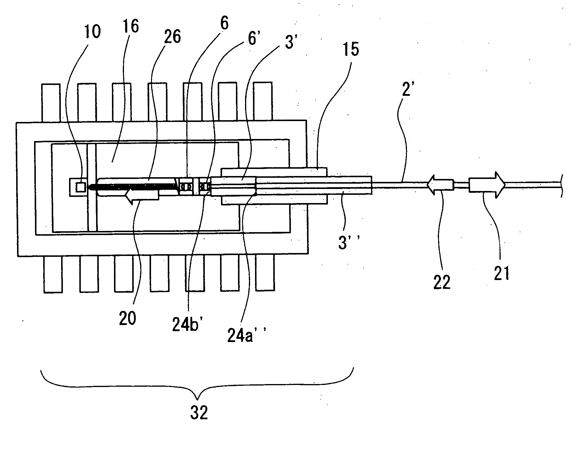
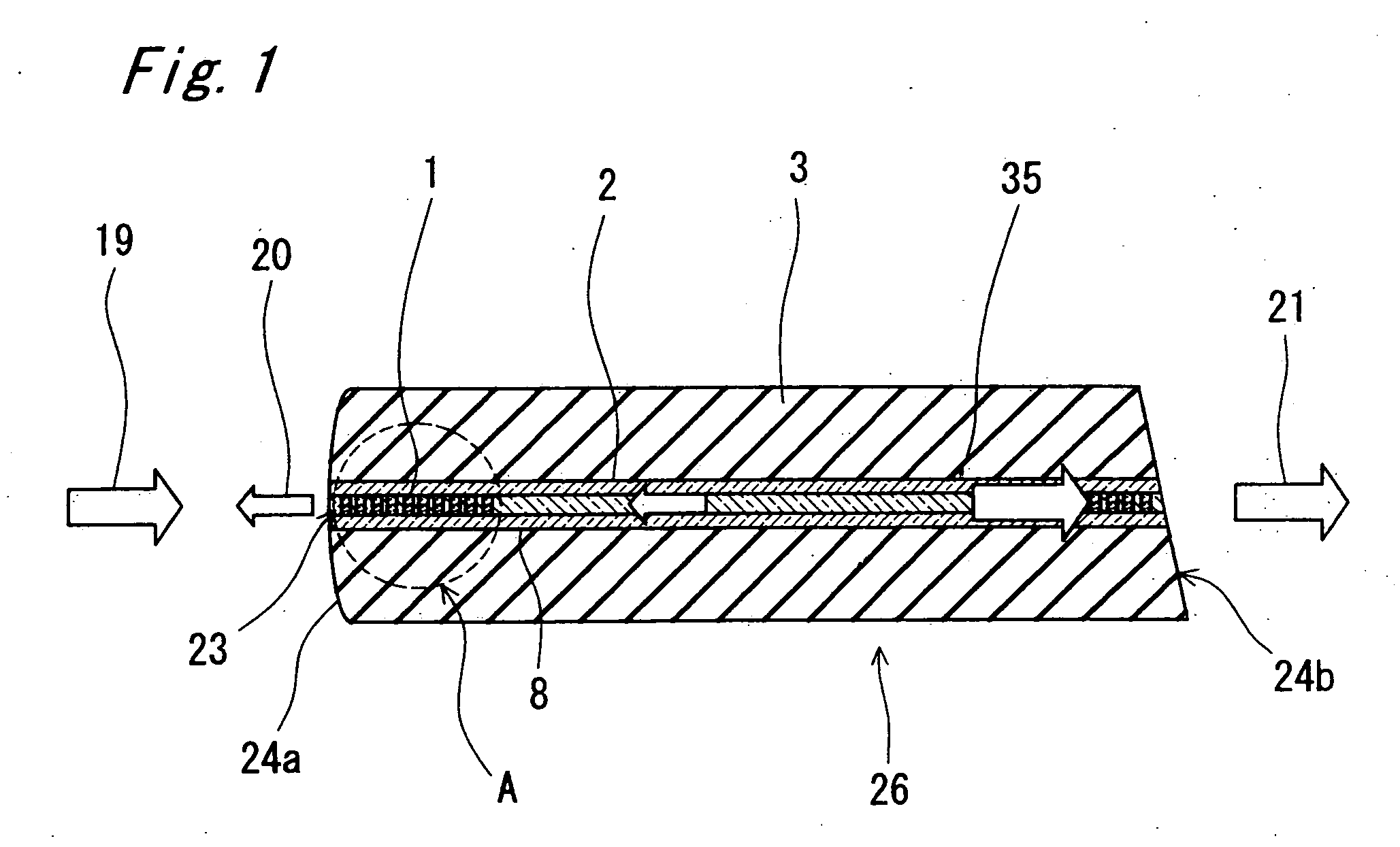
[0077] An external resonator according to the present invention was actually manufactured and mounted on a semiconductor laser module as shown in FIG. 7. An FBG 1 having a center wavelength λB of the reflected light of 1450 nm was manufactured by using a fiber 2 where mode effective refractive index n1=1.525, n2=1.51, Δ=0.00979, and θc=8°, and a phase mask 17 where Λ (MASK)=951 (nm). Here, Δ and θc are calculated in the following equations:

Δ=(1.5252−1.512) / (2×1.5252)=0.00979

θc=sin−1(2×0.00979)½=8.04°

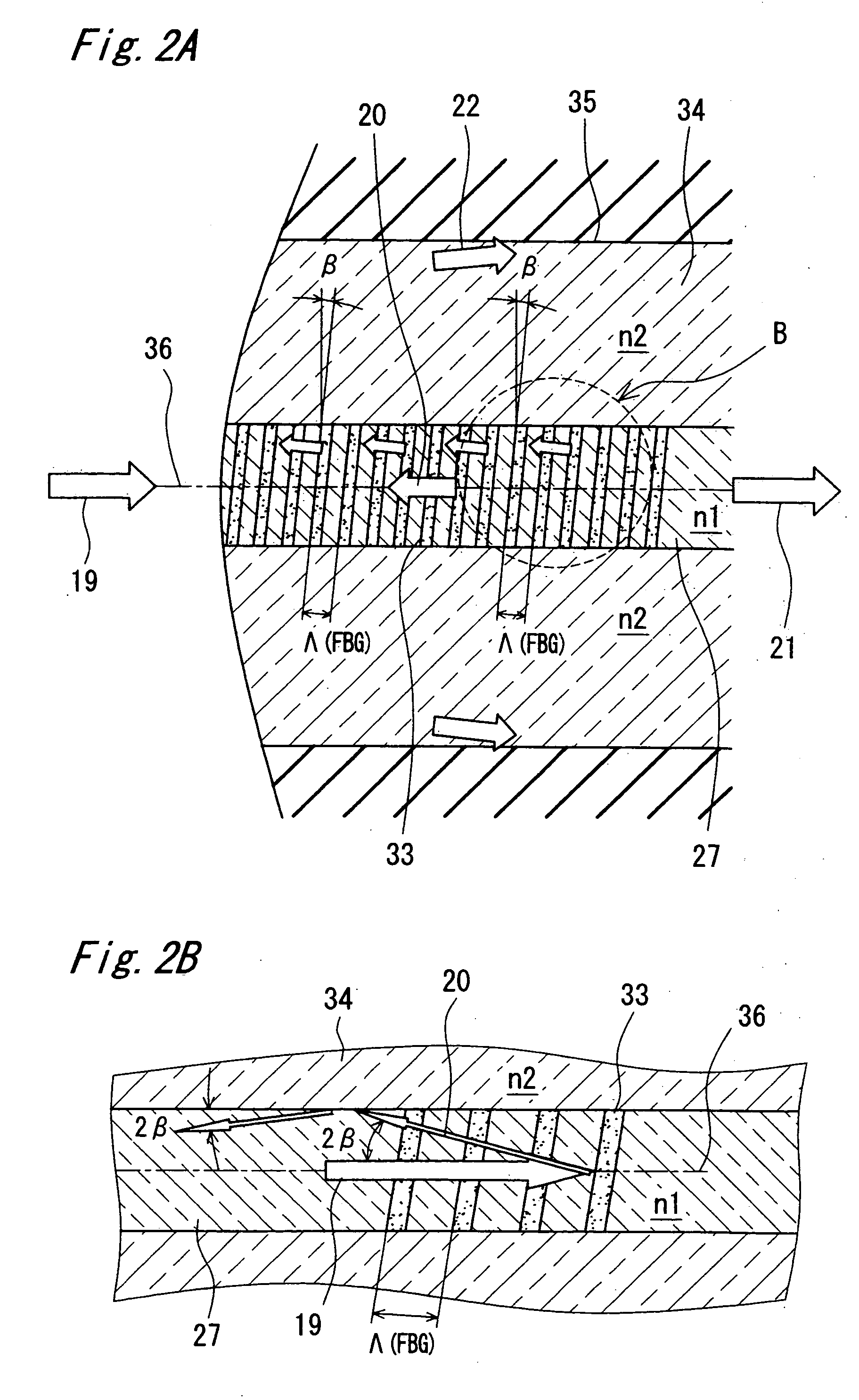
[0078] UV light of an intensity of approximately 500 mW was utilized to irradiate the phase mask 17. In addition, the intensity distribution of the UV light was in the Gaussian state, and the amount of change in the refractive index of the FBG 1 had a distribution in the Gaussian state in the direction of the center axis of the FBG 1. Furthermore, at the time of recording, the fiber was inclined by an inclination angle β from the horizon. Here, β was set to 3° (0°c).

[0079] In this man...


PUM

PropertyMeasurementUnit
lengthaaaaaaaaaa
refractive indexaaaaaaaaaa

Abstract

An external resonator is provided with a fiber having a fiber Bragg grating for reflecting light of a specific wavelength and a ferrule which holds the above described fiber inside thereof. At least some phase gratings from among the respective phase gratings that form fiber Bragg grating are inclined relative to the optical axis of the fiber.

Description

BACKGROUND [0001] 1. Field of the Invention [0002] The present invention relates to an optical fiber provided with a fiber Bragg grating, an external resonator using the optical fiber, and a semiconductor laser module using the external resonator. [0003] 2. Description of the Related Art [0004] It is desirable for a semiconductor laser to provide a stable laser light in terms of its wavelength, as well as its output power, in any environmental conditions. In a Fabry-Perot semiconductor laser, light repeatedly reflects between end surfaces of a laser chip, of which length is not greater than 500 μm, and oscillates in multi-mode. Accordingly, spectrum properties of a laser light tend to spread. Also, if the materials of the semiconductor laser element thermally expand, the refractive index in an active region changes, and thereby, the length of a resonator between end surfaces changes. This results in a change of the oscillation wavelength of laser light. In order to prevent this prob...

Claims


Application Information

Patent Timeline
Patent Type & Authority Applications(United States)
IPC IPC(8): G02B5/26G02B6/02G02B6/34G02B6/42G02F1/025H01S3/08H01S5/00H01S5/022H01S5/024H01S5/026H01S5/10H01S5/125H01S5/14
CPCG02B6/02085G02B6/02138G02B6/29319G02B6/4203G02B6/4206H01S5/005H01S5/146H01S5/02216H01S5/02284H01S5/02415H01S5/02438H01S5/141H01S5/0064H01S5/02251
Inventor OKUTA, MICHITAKASHIGEOKA, YOSHIYUKI
Owner KYOCERA CORP
Why Eureka
Try Eureka