Coil type turn-fin condenser

Inactive Publication Date: 2008-05-06
KOREA BUNDY
View PDF10 Cites 16 Cited by
  • Summary
  • Abstract
  • Description
  • Claims
  • Application Information

AI Technical Summary

Benefits of technology

[0013]The present invention has been made to solve the above problems, and it is an object of the present invention to provide a coil type turn-fin cond

Problems solved by technology

However, there are problems in that since the bending type condenser is manufactured by bending the turn-fin tube 1 twice in order of the primary bending and the secondary bending, the manufacturing process is complicated, and that since both the motor 4 and the blowing fan 5 provided for air to pass between the turn-fin tubes 1 are protruded outwardly, a large mounting space is required.
Further, when a

Method used


Image

  • Coil type turn-fin condenser
  • Coil type turn-fin condenser
  • Coil type turn-fin condenser

Examples


Example

Embodiment 1

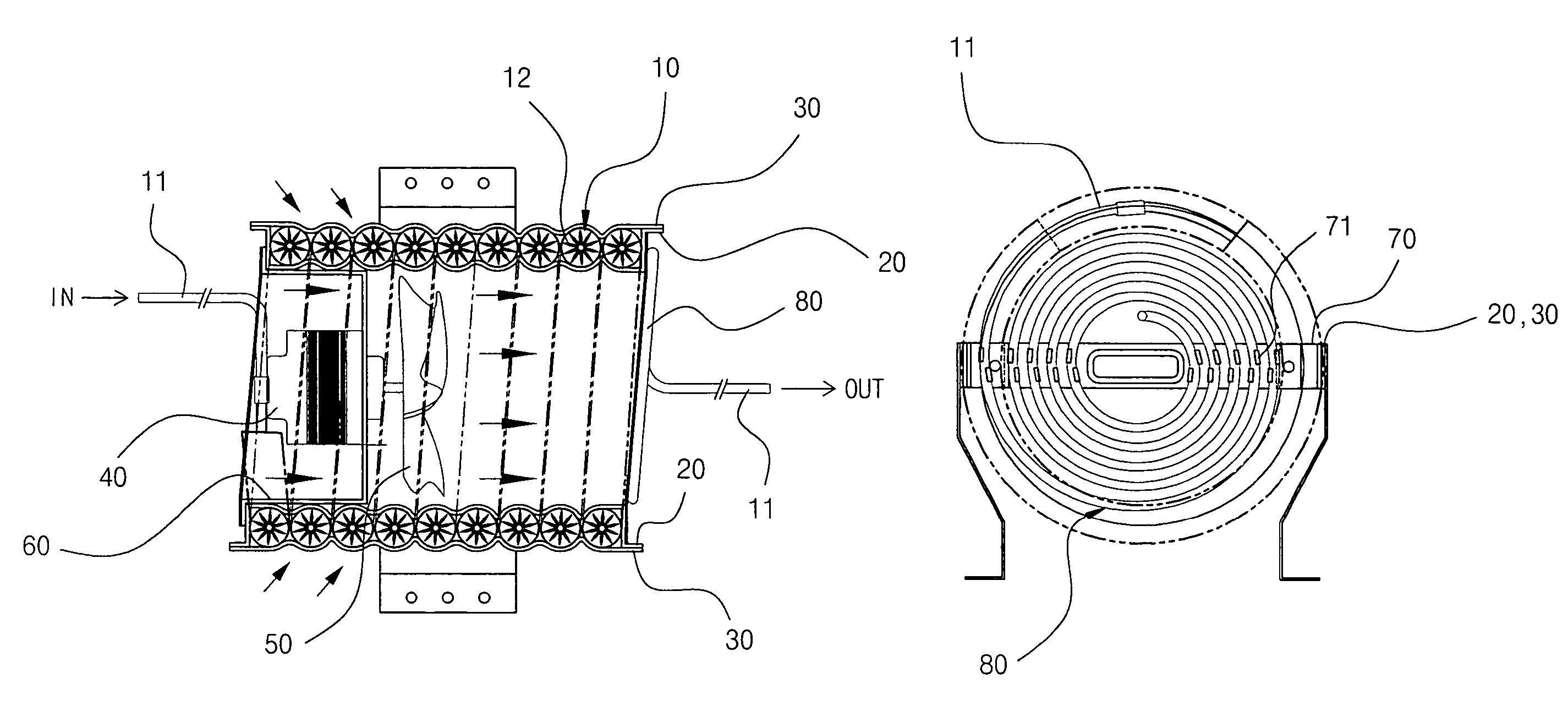
[0032]Referring to FIGS. 4 and 5, a coil type turn-fin condenser according to the present invention is provided with a turn-fin tube 10 with a circular coil shape (which will also be referred to as a “turn-fin tube coil” hereinafter) wound around a tube 11 in which refrigerant flows, on the periphery of which turn-fins 12 are adhesively wound in a spiral shape. The turn-fin tube 10 is provided with an inner bracket 20 and an outer bracket 30, both having a band shape, at the outer and inner surfaces of the turn-fin tube coil, respectively. The inner bracket 20 and an outer bracket 30 are repeatedly formed with arcuate grooves thereon for receiving the turn-fins 12, respectively.

[0033]In an inner space formed by the turn-fin tube coil 10, the coil type turn-fin condenser is mounted with a blowing fan 50 for taking ambient air inside the turn-fin tube coil and a motor 40 for driving the blowing fan 50. The motor 40 is provided in the inner space of the coil while being con...

Example

Embodiment 2

[0047]Referring to FIG. 9, a coil type turn-fin condenser according to the present invention is provided with multiple coils comprised of an inner coil 15 and an outer coil 16 to enhance heat exchange efficiency of the condenser.

[0048]Each of the inner and outer coils 15 and 16 is formed by the turn-fin tube 10 wound around the tube 11 in which a heat exchange medium flows, around the periphery of which the turn-fins 12 are adhesively wound in a spiral shape.

[0049]Except the inner and outer coils 15 and 16, Embodiment 2 has the same components as that of Embodiment 1. Thus, a detailed description of identical components will be omitted hereinafter.

[0050]The outer coil 16 is formed with gaps between the adjacent outer surfaces of the coil for ambient air to pass through the adjacent outer surfaces thereof, and the inner coil 15 is formed inside the outer coil 16 to be separated from the outer coil 16 by a predetermined distance. The inner coil 15 is also formed with the g...


PUM


Abstract

Disclosed herein is a turn-fin condenser. The turn-fin condenser employs a turn-fin tube adhesively wound in a spiral shape around an outer surface of the tube in which refrigerant flows. The condenser comprises a coil type turn-fin tube 10 wound in a coil shape and fixed by inner and outer brackets 20 and 30 surrounding an outer peripheral surface of the coil type turn-fin tube, a motor 40 positioned in an inner space formed by the coil type turn-fin tube 10, a blowing fan 50 for taking ambient air in the coil type turn-fin tube 10 after being driven by the motor 40, and a tube wall 80 spirally wound with tube 11 extending out of the inner and outer brackets 20 and 30 at the rear side of the coil type turn-fin tube 10. The turn-fin condenser is easily manufactured and allows a greater quantity of air contact with turn-fins, thereby enhancing heat exchange efficiency.

Description

PRIORITY REFERENCE TO PRIOR APPLICATIONS[0001]This application claims benefit under 35 U.S.C. §119 of Korean Patent Application No. 10-2003-0027386, filed on Apr. 30, 2003, by inventors Dong-Ha LEE and Mun-Jae IM; and of Korean Utility Model Application No. 20-2004-0000857, filed on Jan. 13, 2004, by inventors Dong-Ha LEE and Mun-Jae IM.BACKGROUND OF THE INVENTION[0002]1. Field of the Invention[0003]The present invention relates to a turn-fin condenser, and more particularly to a coil type turn-fin condenser, which is easily manufactured and includes a structure allowing a greater quantity of air to contact with turn-fins, thereby enhancing heat exchange efficiency.[0004]2. Description of the Related Art[0005]In general, a condenser in an air conditioner is used for radiating heat from a high-temperature, high-pressure vapor phase refrigerant discharged from a compressor and then liquefying the vapor phase refrigerant with a high pressure. In recent years, all major industrialized n...

Claims


Application Information

Patent Timeline
IPC IPC(8): F25D19/00F25B39/04F28F1/32F28F9/00F25D11/00F28F1/36F28D1/047F28D7/02F28F9/013F28F9/26
CPCF25B39/04F28D7/024F28F1/36F28F9/0132
Inventor LEE, DONG HAIM, MUN JAE
Owner KOREA BUNDY
Why Eureka
Try Eureka