Display apparatus

a display apparatus and display device technology, applied in the field of display devices, can solve the problems of troublesome user's frequent on and off of the display device, method may not agree with the intention of the user, and user may continuously use the display device for a long tim

Inactive Publication Date: 2007-12-11
CANON KK
View PDF19 Cites 5 Cited by
  • Summary
  • Abstract
  • Description
  • Claims
  • Application Information

AI Technical Summary

Benefits of technology

[0020]Yet another object of the present invention is to provide a display apparatus which can inform a user of the elapsed time of continuous use and warn the user of continuous long-time use.

Problems solved by technology

However, the above-described conventional apparatus has the problem that a user may continuously use the display apparatus over a long time without noticing the lapse of use time.
In addition, the conventional display which is used as display means for a game or a computer has the problem that a user often tends to immerse himself / herself in a display picture and continuously wear the display apparatus over a long time, as well as the problem that it is troublesome for the user to frequently put on and take off the display apparatus.
Furthermore, regarding the display apparatus shown in FIG. 1, the user may continuously use the display apparatus over a long time without noticing the lapse of use time.
Although there is a method of displaying clock information in the display 1901 to prevent this problem, this method may not agree with the intention of the user, because the display apparatus is intended to create virtual reality.

Method used


Image

  • Display apparatus
  • Display apparatus
  • Display apparatus

Examples


first embodiment

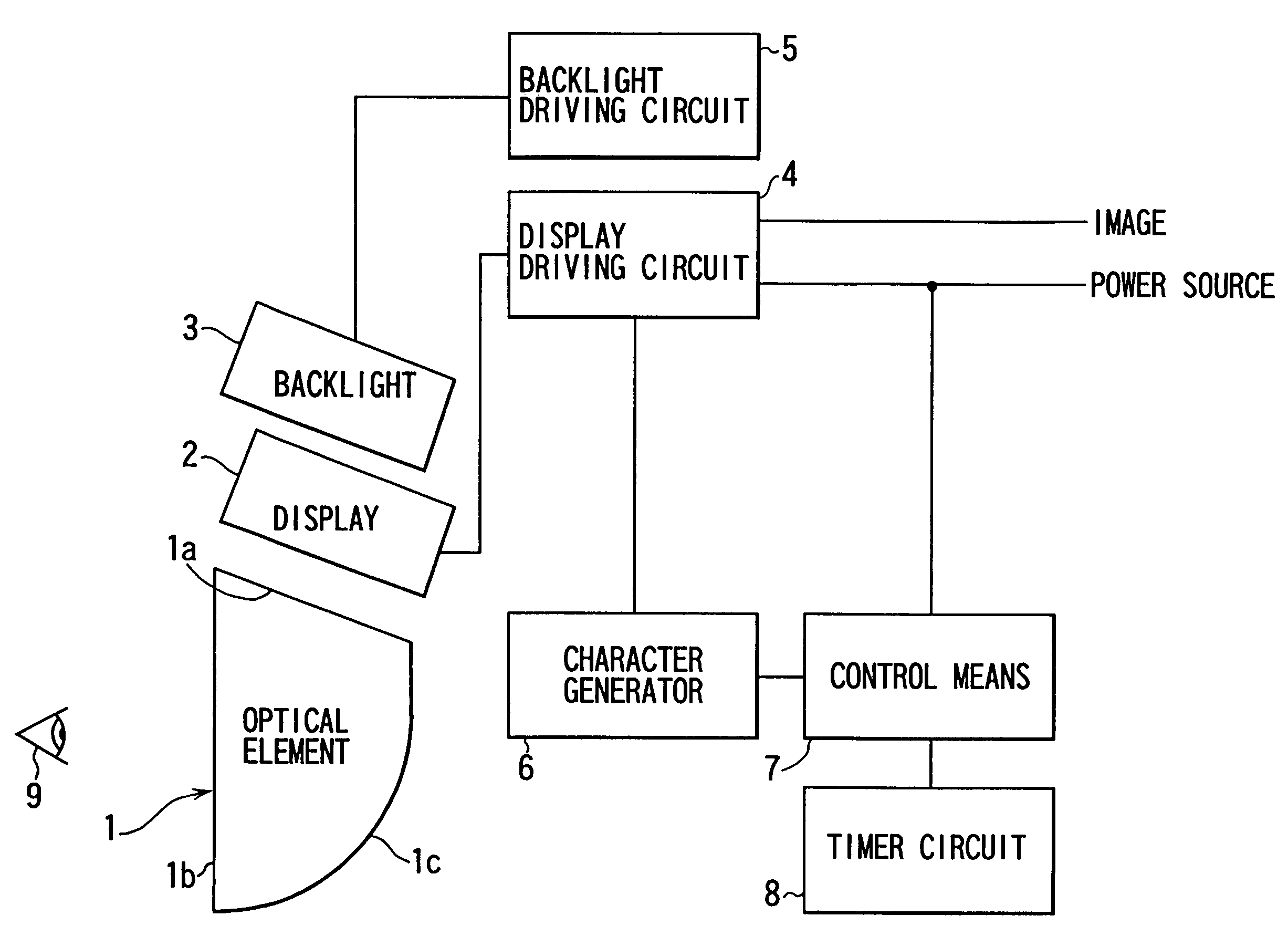
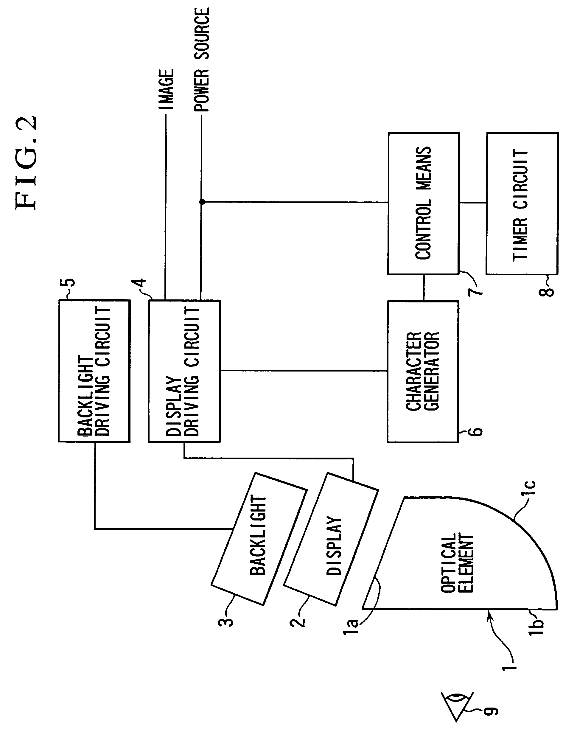
[0043]A first embodiment of the present invention will be described below with reference to FIGS. 2 to 5. FIG. 2 is a block diagram showing the arrangement of a display apparatus (head-mounted display apparatus) according to the first embodiment of the present invention. The arrangement shown in FIG. 2 includes an optical element 1, a display 2 such as a liquid crystal display (liquid crystal display panel), a backlight 3, a display driving circuit 4, a backlight driving circuit 5, a character generator 6, control means 7 such as a microcomputer, and a timer circuit 8. Reference numeral 9 denotes a pupil of a user. Although an illustration is omitted for the sake of simplicity, the user has a pair of right and left pupils, and the optical element 1, the display 2, the backlight 3, the display driving circuit 4 and the backlight driving circuit 5 are provided in pairs each.

[0044]The optical element 1, the display 2, the backlight 3, the display driving circuit 4, the backlight drivin...

second embodiment

[0050]A second embodiment of the present invention will be described below with reference to FIGS. 6 to 8. FIG. 6 is a block diagram showing the arrangement of a display apparatus according to the second embodiment of the present invention. In FIG. 2, identical reference numerals are used to denote parts identical to those of the first embodiment shown in FIG. 1. The arrangement of FIG. 6 differs that of FIG. 2 in that an LED driving circuit 12, an LED 13, a timer time extending switch 14, a power source control circuit 15 and a power source switch 16 are added to the arrangement of FIG. 2, and the second embodiment is arranged to inform the user of the lapse of the timer time set by the user operating the timer circuit 8, by lighting the LED 13 by means of the LED driving circuit 12 as shown in FIG. 8.

[0051]Furthermore, the second embodiment shown in FIG. 6 is arranged so that the power source control circuit 15 automatically turns off the power source switch 16 after the timer tim...

third embodiment

[0057]A third embodiment of the present invention will be described below with reference to FIGS. 9 and 10. FIG. 9 is a block diagram showing the arrangement of a display apparatus according to the third embodiment of the present invention. In FIG. 9, identical reference numerals are used to denote parts identical to those of the second embodiment shown in FIG. 6. The arrangement of FIG. 9 differs that of FIG. 6 in that an arbitrary timer operating switch 17 is provided in place of the timer time extending switch 14 in the arrangement of FIG. 6.

[0058]If the user turns on the power source switch 16 while operating the arbitrary timer operating switch 17, or if the user operates the arbitrary timer operating switch 17 immediately after turning on the power source switch 16, the user can arbitrarily select a timer time to be set. If such an operation is not performed, the timer time preset by the timer circuit 8 is set to a predetermined preset time.

[0059]The operation of the display a...


PUM


Abstract

A display apparatus includes a display unit, a time setting unit, a detection unit and an image changing unit. The display unit is configured to display a color image. The time setting unit is configured to set a time. The time to be set by the time setting unit can be changed by a user. The detection unit is configured to detect whether the time set by the time setting unit is passed. The image changing unit is configured to change a color image to be displayed on the display unit to a monochrome image so as to warn the user that the time set by the time setting unit is passed, if the detection unit detects that the time set by the time setting unit is passed.

Description

CROSS-REFERENCE TO RELATED APPLICATIONS[0001]This application is a divisional of application Ser. No. 08 / 864,335, filed May 28, 1997 now U.S. Pat. No. 6,630,914.BACKGROUND OF THE INVENTION[0002]1. Field of the Invention[0003]The present invention relates to a so-called head-mounted type of display apparatus (head-mounted display) which permits a user to view a display image with the display apparatus being mounted on a predetermined portion of the user, such as the head or the face.[0004]2. Description of Related Art[0005]Conventionally, this kind of display apparatus has not had the function of informing a user himself / herself how long the user has been using the display apparatus.[0006]In recent years, this kind of display apparatus has been used in more and more applications which enable users to view images or the like. Computer games are the most popular of such applications. Unlike normal television screens, this kind of display apparatus can easily create a closed space, so t...

Claims


Application Information

Patent Timeline
Patent Type & Authority Patents(United States)
IPC IPC(8): G09G5/00G02B27/00G02B27/01H04N5/64G09G3/00G09G3/14G09G3/20G09G3/36
CPCG02B27/017G09G3/14G09G3/3611G02B2027/0118
Inventor TAMEKUNI, YASUHIROFUJIWARA, AKIHIROMOROFUJI, TSUYOSHI
Owner CANON KK
Why Eureka
Try Eureka