Device for preparation of plastic materials for recycling purposes

a technology for plastic materials and recycling, applied in the field of plastics material preparation devices, to achieve the effect of less space, improved plasticizing properties, and intensive work

Active Publication Date: 2007-12-18
EREMA ENG RECYCLING MASCH & ANLAGEN GMBH
View PDF12 Cites 29 Cited by
  • Summary
  • Abstract
  • Description
  • Claims
  • Application Information

AI Technical Summary

Benefits of technology

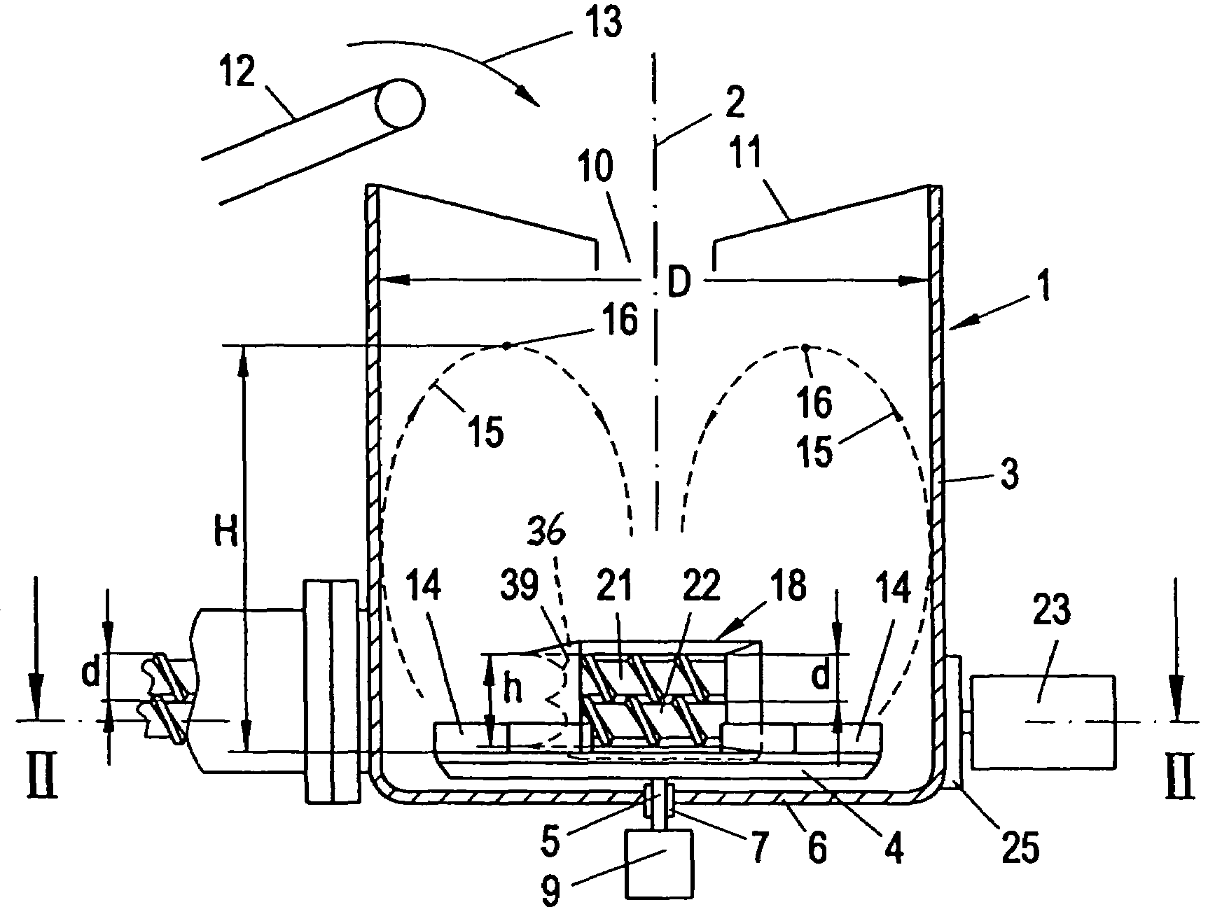
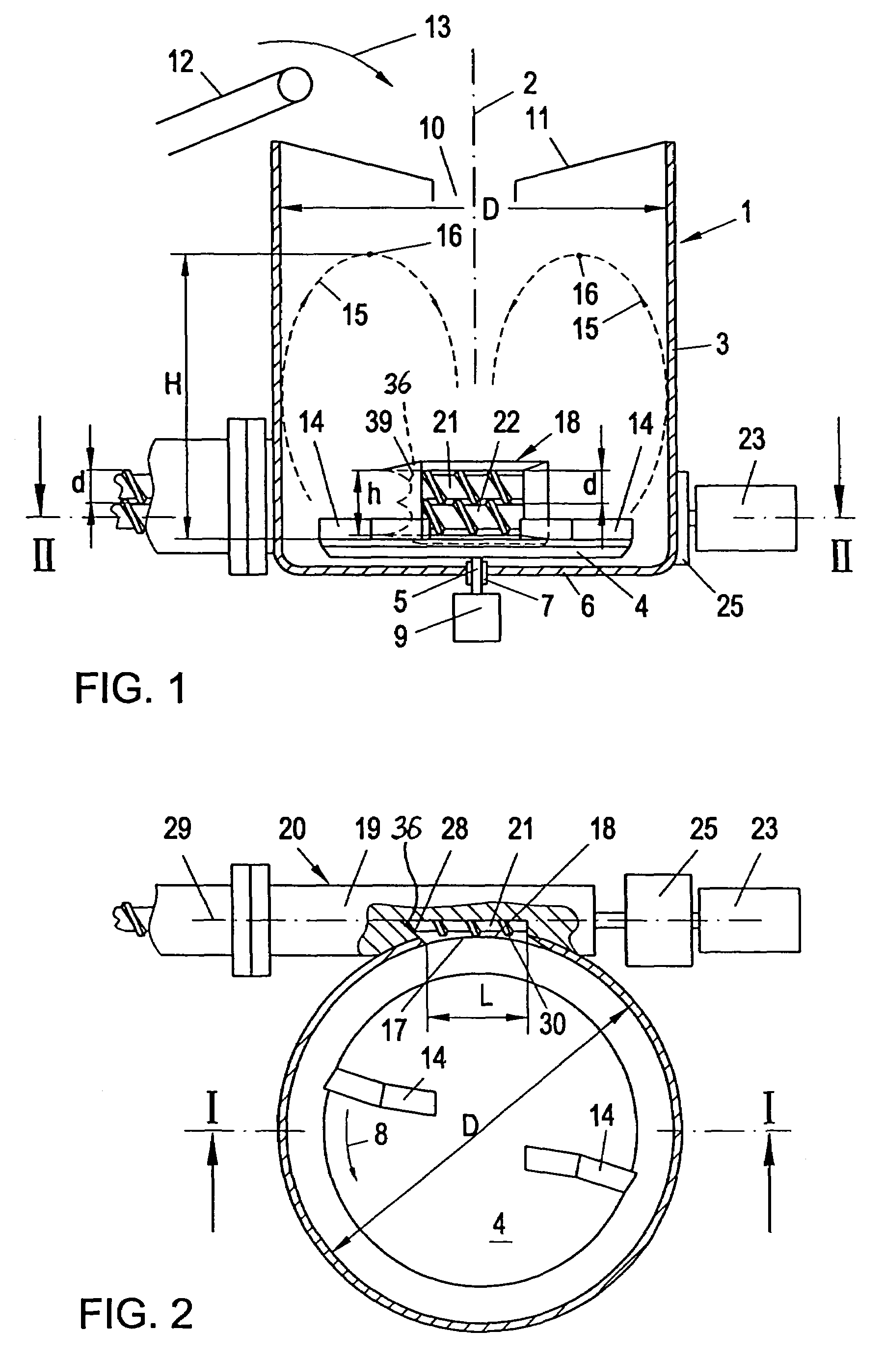
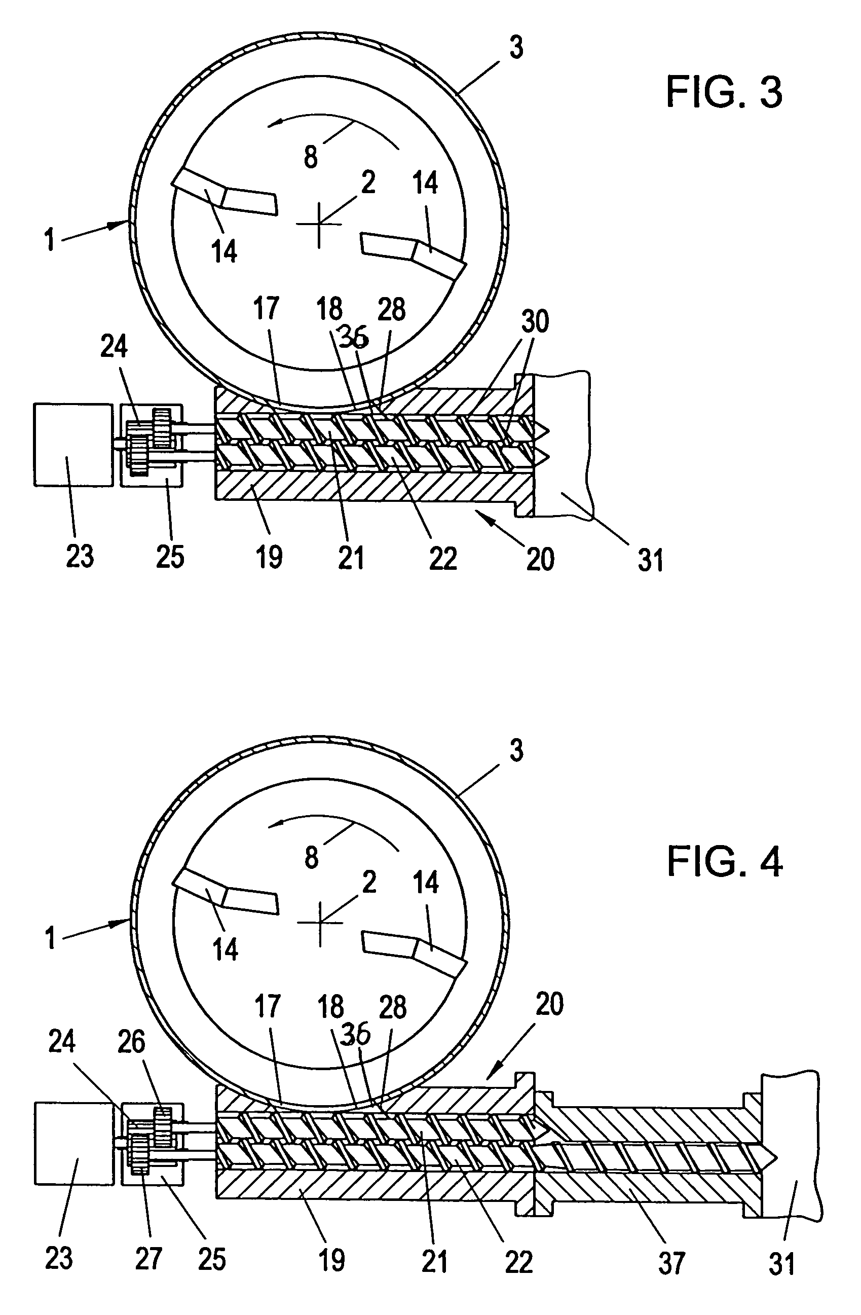
[0004]An object of the present invention is to overcome these difficulties and improve a device of the initially described type in such a way that the material to be processed is fed as uniformly as possible into the feed opening of the screw housing, the feed opening being connected to the outlet opening, so that a uniform output is achieved at the delivery end of the screw, in particular of a plasticizer or agglomerator. The invention achieves this object in that the widening, seen in the direction of the axis of the housing of the screw, extends over part of the circumference of the turns of the adjacent screw, preferably into the region of the screw axis, so that the screw-side edge of this widening forms an uninterrupted shearing edge cooperating with these screw turns. This produces a constant infeed of the material to be processed into the feed opening of the screw, even when the material in the container is soft through heating. It may be assumed that this improved mode of operation is attributable to the comparatively long shearing edge formed by the screw-side edge of the widening. A further essential advantage of the design according to the invention lies in the fact that the cooled grooved sleeve, which has hitherto usually been necessary in the infeed region and which is subjected to considerable wear, is no longer required. This not only represents a cost saving, but also brings with it the advantage of a lower starting torque for the drive motor.

Problems solved by technology

Essentially, the known devices operate satisfactorily, but frequently have difficulties when charging the apparatus connected to the outlet opening, in particular when this apparatus is a plasticizer or agglornerator.
The aforementioned difficulties are caused, among other things, by the fact that the material to be processed usually varies greatly, both with respect to the chemical composition of the material and with respect to its external constitution (degree of soiling, particle size, particle shape, etc.).

Method used


Image

  • Device for preparation of plastic materials for recycling purposes
  • Device for preparation of plastic materials for recycling purposes
  • Device for preparation of plastic materials for recycling purposes

Examples


Embodiment Construction

[0025]The device according to FIGS. 1, 2 and 6 is a shredder / extruder combination with a twin screw and has a container 1 with a vertical axis 2 and a circular cross-section, the side wall 3 of which extends substantially cylindrically. A carrier plate 4 rotates about the axis 2 in the container 1 in the direction of the arrow 8 (FIG. 2) and sits on a shaft 5 which extends through the base 6 of the container 1 in a sealed manner and is rotatably mounted in the base 6 in bearings 7. The shaft 5 is rotatably driven by a motor 9.

[0026]The top of the container 1 has an inlet opening 10 for the material to be processed, advantageously in a funnel-shaped covering wall 11. If the material is to be processed under vacuum, an evacuator is connected to the container 1, and the inlet opening 10 is provided with a sluice which can advantageously also be evacuated. The material to be processed is fed to the inlet opening 10 by a feeder 12, e.g. a conveyor belt, and dropped into the opening 10 in...


PUM

PropertyMeasurementUnit
angleaaaaaaaaaa
angleaaaaaaaaaa
angleaaaaaaaaaa

Abstract

A device for the preparation of plastics material for recycling purposes has a container (1) with an upper inlet opening (10) for the material. In the container (1), at least one tool (14) rotates about the vertical container axis. This tool feeds the treated material through an outlet opening (17) which is arranged at the bottom of the container (1) and to which the housing (19) of at least one screw (21, 22) is connected. That side wall (28) of the feed opening (18) at which the tool (14) discharges defines a widening (36) extending continuously towards the screw axis. This widening (36) extends over part of the circumference of the screw turns (30) so that the screw-side edge of this widening (36) forms an uninterrupted shearing edge (39) co-operating with the screw turns (30).

Description

[0001]This application is the National Stage of International Application PCT / AT04 / 00166 filed on May 11, 2004.BACKGROUND OF THE INVENTION[0002]The invention relates to a device for the preparation of plastics material for recycling purposes, in particular thermoplastic plastics material, comprising a container into which the material to be processed is fed from above through an inlet opening, and at least one mixing and / or comminuting tool arranged in the container and rotating about the vertical axis of the container, wherein the material treated by this tool is fed through an outlet opening which is arranged at the bottom of the container and to which the feed opening of a housing of at least one screw is fluidly connected, the housing being connected, preferably tangentially, to the container, and wherein that side wall of the feed opening at which the tool discharges, seen in section, defines a widening of the feed opening, the widening extending continuously towards the axis o...

Claims


Application Information

Patent Timeline
Patent Type & Authority Patents(United States)
IPC IPC(8): B02C18/12B02C18/22B29C47/10B29B13/10B29B17/00B29B17/04B29C48/03B29C48/50B29C48/92
CPCB29B13/10B29B17/0036B29B17/0412B29C47/92B29C47/585B29C47/1009B29B2017/048B29K2101/12B29K2105/26B29C47/0009Y02W30/62B29C48/03B29C48/286B29C48/501
Inventor BACHER, HELMUTSCHULZ, HELMUTHWENDELIN, GEORG
Owner EREMA ENG RECYCLING MASCH & ANLAGEN GMBH
Why Eureka
Try Eureka