Method for processing synthetic materials for the purpose of recycling

a synthetic material and recycling technology, applied in the field of thermoplastic plastics materials, can solve the problems of a twin-screw design, the relative high cost previously had to be considered, and the cost of the twin-screw design, etc., and achieve the effect of less space, improved plasticizing properties, and constant infeed of processing materials

Active Publication Date: 2007-10-02
EREMA ENG RECYCLING MASCH & ANLAGEN GMBH
View PDF5 Cites 25 Cited by
  • Summary
  • Abstract
  • Description
  • Claims
  • Application Information

AI Technical Summary

Benefits of technology

[0009]This construction according to the invention produces a constant infeed of the processing material to the screws, even when the material in the container is softened through heating. As the screw length can be kept shorter than in single-screw designs, shorter by approximately half in a twin-screw design, substantially less space is required for the same output of the device. Better plasticizing properties are produced in the wedge region of the screws because there the material is particularly intensively worked by shearing and kneading. It has also been shown, with respect to the screw geometry, that this type of design is less sensitive to the processing of different types of plastics, with the result that the device is more universally usable.
[0010]A further advantage of the design according to the invention lies in the fact that the cooled grooved sleeve, which has hitherto usually been necessary in the infeed region and which is subjected to considerable wear, is no longer required. This not only represents a cost saving, but also brings with it the advantage of a lower starting torque for the drive motor.

Problems solved by technology

With respect to twin-screw extruders, the relatively high costs previously had to be considered, but it is the inventors' experience that the complicated measures which were necessary in single-screw designs in order to achieve some degree of uniform infeed behavior come close to the cost of a twin-screw design.

Method used


Image

  • Method for processing synthetic materials for the purpose of recycling
  • Method for processing synthetic materials for the purpose of recycling
  • Method for processing synthetic materials for the purpose of recycling

Examples


Embodiment Construction

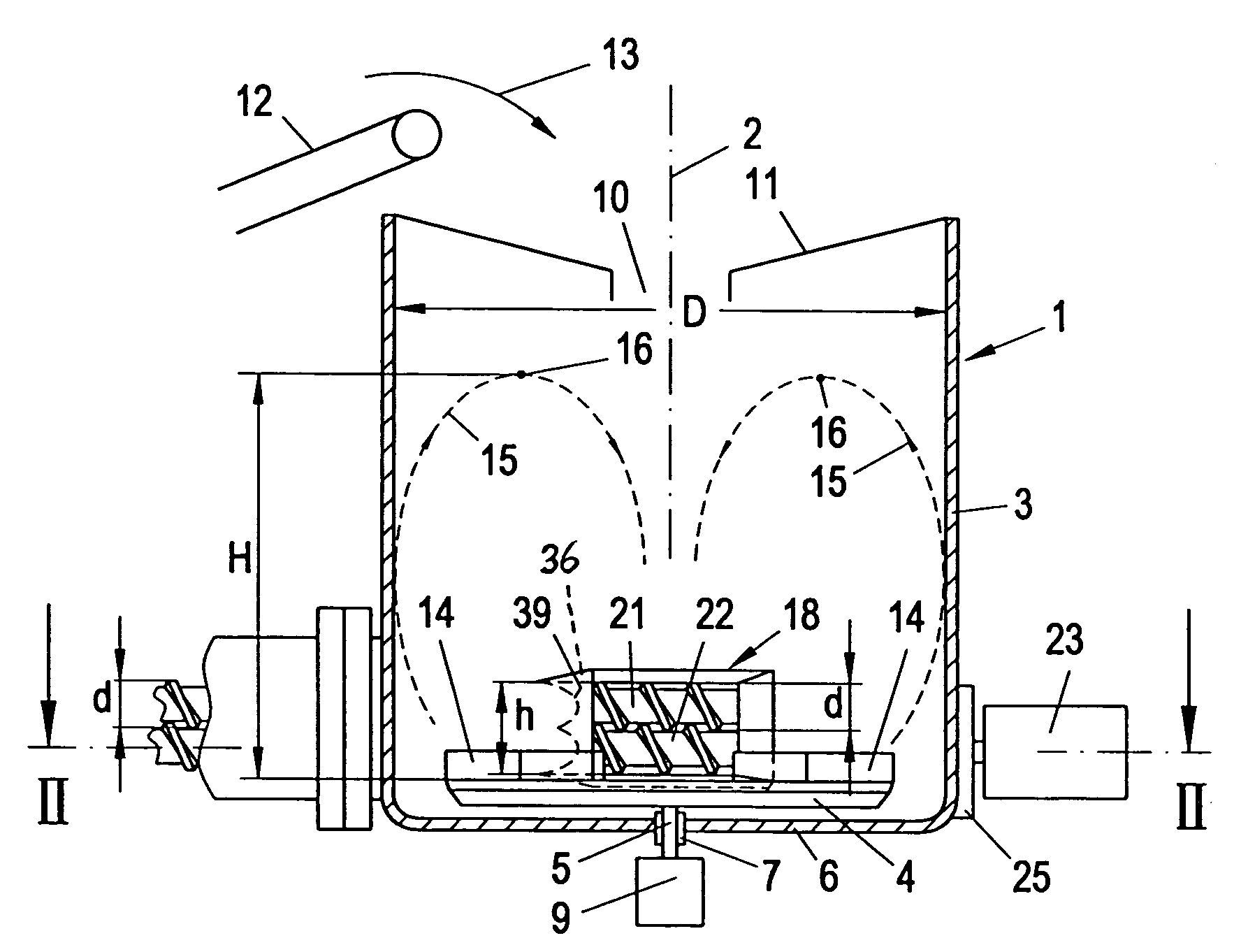
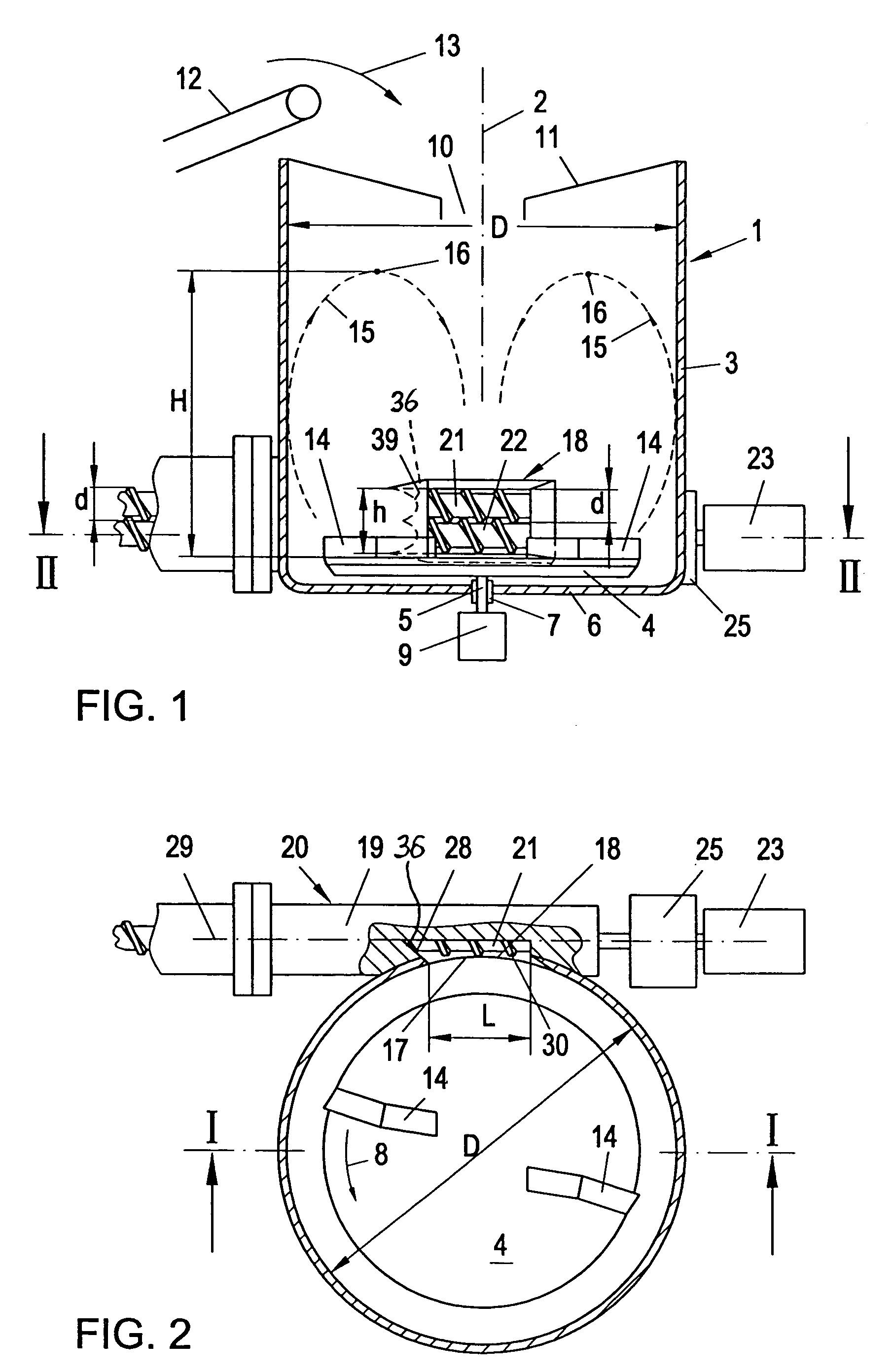
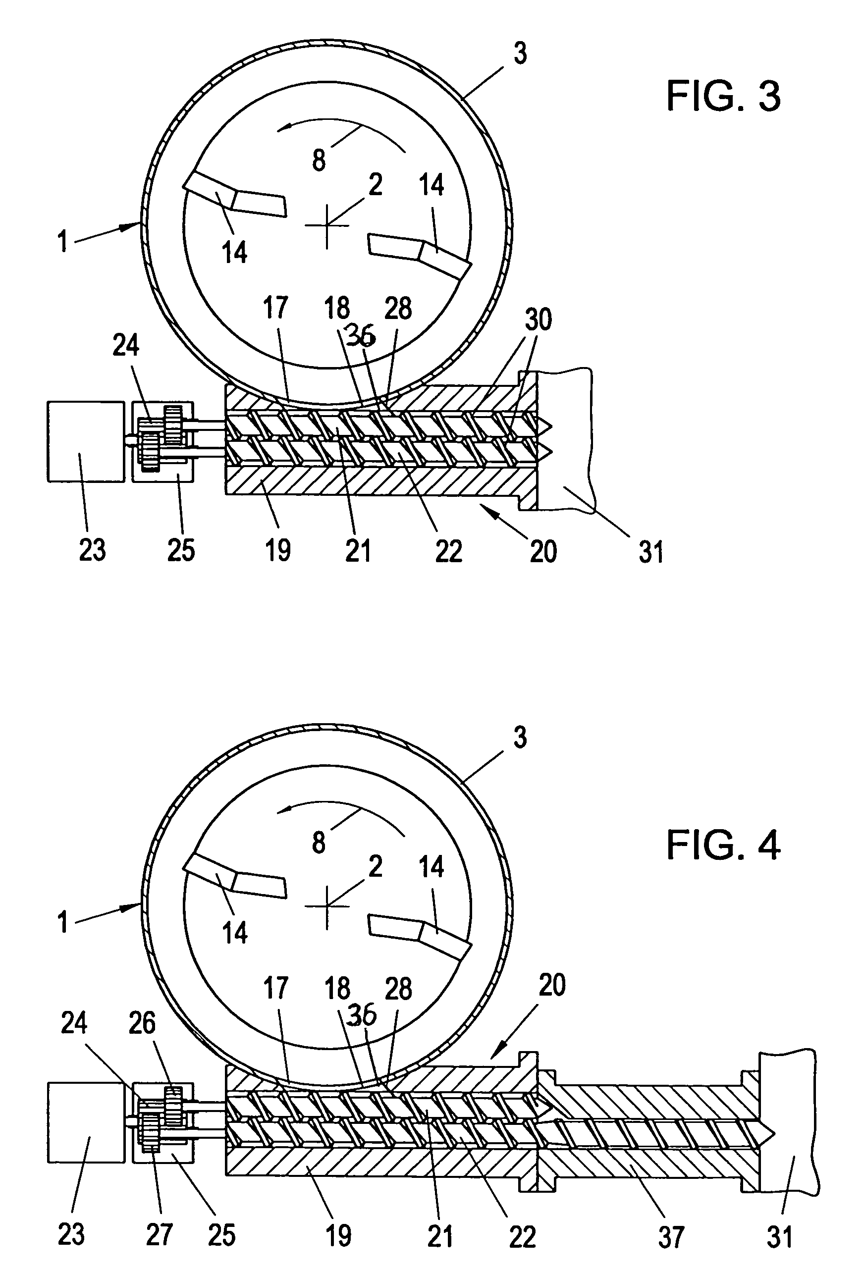
[0030]In the device according to FIGS. 1, 2, 6 and 7, the device forms a shredder / extruder combination with a twin screw and has a container 1 with a vertical axis 2 and a circular cross-section, the side wall 3 of which extends substantially cylindrically. A carrier plate 4 rotates about the axis 2 in the container 1 in the direction of the arrow 8 (FIG. 2) and sits on a shaft 5 which extends through the base 6 of the container 1 in a sealed manner and is rotatably mounted in the base 6 in bearings 7. The shaft 5 is rotatably driven by a motor 9.

[0031]The top of the container 1 has an inlet opening 10 for the material to be processed, advantageously in a funnel-shaped covering wall 11. If the material is to be processed under vacuum, an evacuator is connected to the container 1, and the inlet opening 10 is provided with a sluice which can advantageously also be evacuated. The material to be processed is fed to the inlet opening 10 by a feeder 12, e.g. a conveyor belt, and dropped i...


PUM

PropertyMeasurementUnit
angleaaaaaaaaaa
angleaaaaaaaaaa
angleaaaaaaaaaa

Abstract

A device for the preparation of, preferably thermoplastic, plastics material for recycling purposes has a container (1) in which at least one rotating mixing and/or comminuting tool (14) is arranged. The material thus treated is fed through an outlet opening (17) which is arranged at the bottom of the container (1) and to which the feed opening (18) of a housing (19) is fluidly connected. In this housing are arranged at least two screws (21, 22) which are jointly charged with material. The diameter (D) of the container (1) and the diameter (d) of each of the screws (21, 22) are in the relationship
D=103{square root over (d2K)},
where
  • D is the inner diameter of the circular cylindrical container (1) or the inner diameter of a hypothetical circular cylindrical container converted to the same capacity and having the same effective height,
  • d is the screw diameter, and
  • K is a constant greater than or equal to 50.

Description

BACKGROUND OF THE INVENTION[0001]The invention relates to a device for the preparation of plastics material for recycling purposes, in particular thermoplastic plastics material, comprising a container which has an inlet opening at the top for the material to be processed, wherein at least one movable mixing and / or comminuting tool is arranged in the container and preferably rotates about the vertical container axis, and the material treated by this tool is fed through an outlet opening which is arranged at the bottom of the container and to which the feed opening of a housing of an apparatus, preferably a plasticizer or agglomerator, is fluidly connected, the apparatus comprising a screw.[0002]Devices of this type are known, e.g. EP 1 173 315 or WO-A-01 / 39948, wherein the plasticizer or agglomerator usually has an extruder screw which feeds the material conveyed by it directly to the following processing stage, usually a granulator. However, the screw can also be a simple conveyor ...

Claims


Application Information

Patent Timeline
Patent Type & Authority Patents(United States)
IPC IPC(8): B02C15/00B01F27/93B29B13/10B29B17/00B29B17/04B29C48/04B29C48/285B29C48/50
CPCB29B13/10B29B17/0036B29B17/0412B29C47/10B29C47/585B29B2017/046B29K2105/26B29C47/0011B29K2101/12B29B2017/048B29C48/04B29C48/285B29C48/501B29B17/00Y02W30/62
Inventor BACHER, HELMUTSCHULZ, HELMUTHWENDELIN, GEORG
Owner EREMA ENG RECYCLING MASCH & ANLAGEN GMBH
Why Eureka
Try Eureka