Coaxial connector with a cable gripping feature

a technology of coaxial cable and gripping feature, which is applied in the direction of coupling device connection, coupling parts engagement/disengagement, two-part coupling device, etc. it can solve the problems of increasing installation difficulty, increasing the difficulty of sealing the interior of the connector from outside elements, and increasing the diameter of the cable. , to achieve the effect of reducing the diameter of the barb, enhancing the gripping effect, and increasing the retention

Active Publication Date: 2007-12-18
PPC BROADBAND INC
View PDF233 Cites 70 Cited by
  • Summary
  • Abstract
  • Description
  • Claims
  • Application Information

AI Technical Summary

Benefits of technology

[0009]It is a further object of the present invention to provide a coaxial cable having structure to enhance gripping of a coaxial cable, especially a small diameter coaxial cable.
[0013]The locking sleeve preferably includes a plurality of flexible fingers defining the forward connector insertion end of the sleeve. In this manner, at least two adjacent fingers of the sleeve can be connected by a web to increase gripping strength. Also, the flexible finger can include a lateral groove formed therein to enhance flexibility of the finger.
[0015]To further enhance gripping of the cable, the annular post disposed within the connector body preferably includes a first radially outwardly projecting barb disposed at a rearward end thereof and a second radially outwardly projecting barb disposed forward of the first barb. More specifically, the post may include a shoulder portion in press-fit engagement with the connector body and an annular tubular extension extending between the shoulder portion and the first and second barbs and having a maximum outer diameter. The first and second barbs thus have an outer diameter greater than the maximum outer diameter of the annular tubular extension.
[0016]The gripping action of the fingers increases cable retention. This allows reducing the diameter of the barb on the post which facilitates cable insertion. Therefore, the present invention allows a user to insert a coaxial shielded cable into the coaxial connector with less force than current connectors to prevent buckling of the coaxial shielded cable. The present invention also allows for the coaxial shielded cable to be held securely within the coaxial connector without buckling the coaxial shielded cable.

Problems solved by technology

A problem with current coaxial connectors is that they often do not adequately grip the coaxial shielded cables, particularly with smaller diameter coaxial cables.
Such expansion requires increased cable insertion force, making installation more difficult.
Moreover, sealing the interior of the connector from outside elements also becomes more challenging with smaller diameter cables.

Method used


Image

  • Coaxial connector with a cable gripping feature
  • Coaxial connector with a cable gripping feature
  • Coaxial connector with a cable gripping feature

Examples


Embodiment Construction

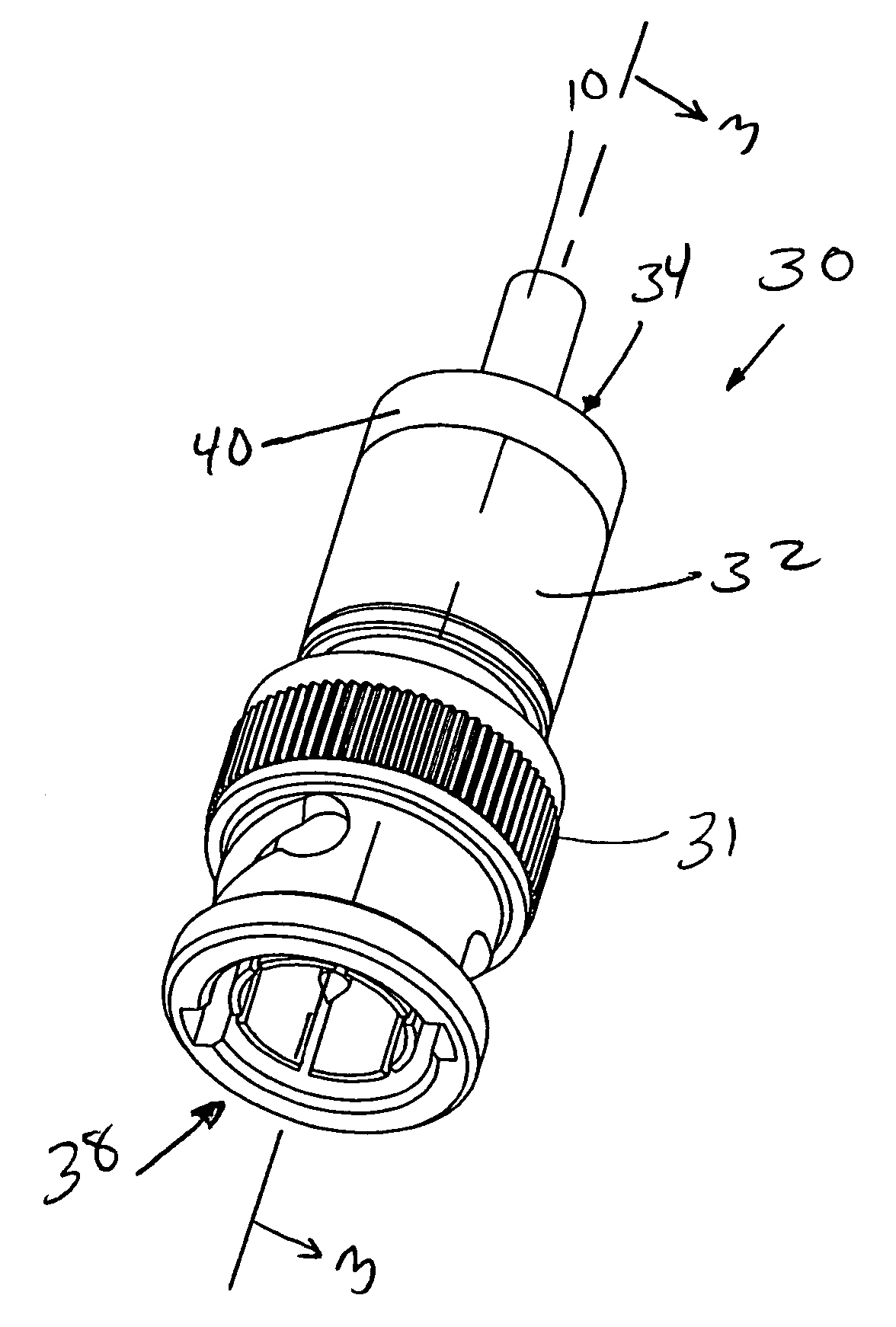
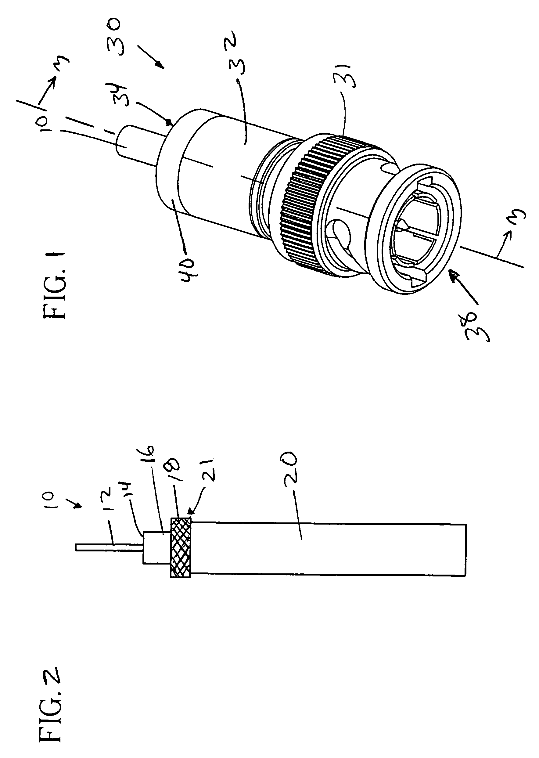
[0029]Referring to FIG. 1, a coaxial connector 30 in accordance with the present invention is shown. The connector 30 has a housing 32 (sometimes referred to as a “connector body” or “collar”) having a first end 34 and a sleeve 40 which accepts a coaxial shielded cable 10. Positioned opposite the first end 34 is a second end 38 having a twistlock device 31 used to attach the connector 30 to the desired mating device (not shown). The connector 30 is shown fully assembled and is a compact design. The housing 32, and sleeve 40 can have a cylindrical outer profile.

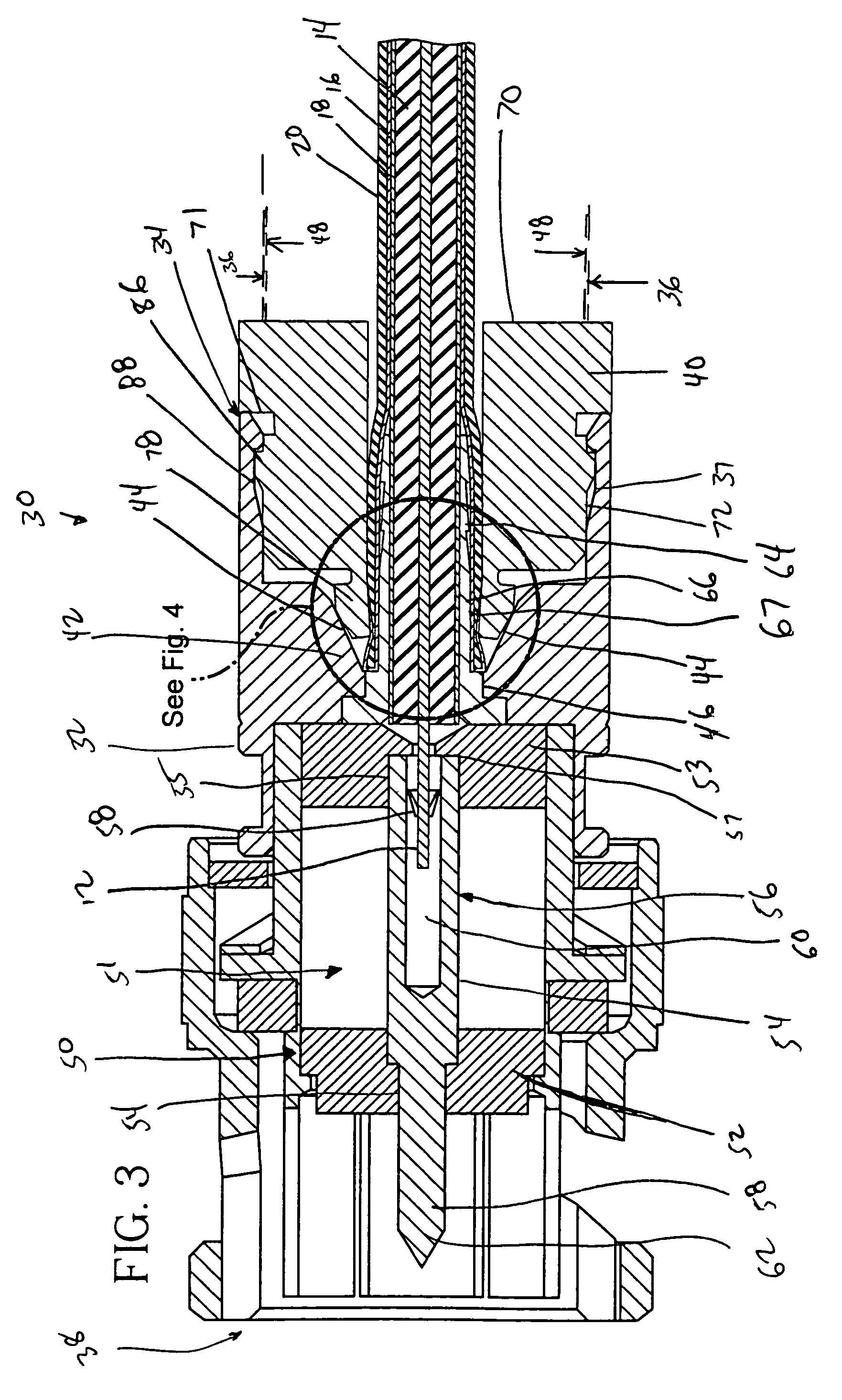
[0030]A typical coaxial shielded cable 10 is shown in FIGS. 1 and 3. The coaxial shielded cable 10 has a center conductor 12 having a dielectric covering 14 surrounding it. The dielectric layer 14 is covered by a foil 16 and a metallic braid 18. The braid 18 is then covered by an outer covering 20 which can be plastic or any other insulating material.

[0031]To prepare the coaxial shielded cable 10 for use with the connector 30,...


PUM


Abstract

A coaxial cable connector including a connector body having a rearward sleeve receiving end and an inner engagement surface and an axially movable locking sleeve seated in the rearward sleeve receiving end of the connector body is disclosed. The locking sleeve has a rearward cable receiving end and an opposite forward connector insertion end. The forward connector insertion end is formed with at least one flexible finger for gripping a cable inserted in the sleeve when the locking sleeve is moved from a first position to a second position.

Description

CROSS-REFERENCE TO RELATED APPLICATIONS[0001]This application claims the benefit of U.S. Provisional Application No. 60 / 660,653, filed on Mar. 11, 2005.BACKGROUND OF THE INVENTION[0002]The present invention relates generally to connectors for terminating coaxial cable and more particularly to a coaxial cable connector having a cable gripping feature.[0003]It has long been known to use connectors to terminate coaxial cable so as to connect a cable to various electronic devices such as televisions, radios and the like. Prior art coaxial connectors generally include a connector body having an annular collar for accommodating a coaxial cable, an annular nut rotatably coupled to the collar for providing mechanical attachment of the connector to an external device and an annular post interposed between the collar and the nut. A resilient sealing O-ring may also be positioned between the collar and the nut at the rotatable juncture thereof to provide a water resistant seal thereat. The col...

Claims


Application Information

Patent Timeline
Patent Type & Authority Patents(United States)
IPC IPC(8): H01R9/05H01R24/38H01R24/28
CPCH01R9/0524H01R9/0521H01R13/5812H01R9/05H01R13/639
Inventor RODRIGUES, JULIO F.
Owner PPC BROADBAND INC
Why Eureka
Try Eureka