
Fuel cell stack

a fuel cell and stack technology, applied in the field of fuel cell stacks, can solve the problems of large devices, large devices, and low power generation efficiency of separate heat generators, and achieve the effect of facilitating the startup of fuel cells

Active Publication Date: 2007-12-18
EQUOS RES
View PDF6 Cites 6 Cited by
  • Summary
  • Abstract
  • Description
  • Claims
  • Application Information

AI Technical Summary

Benefits of technology

[0007]An object of the present invention is to facili

Problems solved by technology

However, it is known that when starting the power generation under freezing conditions, the fuel cell is required to have a constant temperature, otherwise power generation efficiency drops off.
However, providing a separate heat generator consumes extra electric power, and makes the device large-sized.
In addition, there is also the problem that increasing the power generation gradually requires a long time to reach a normal state.

Method used


Image

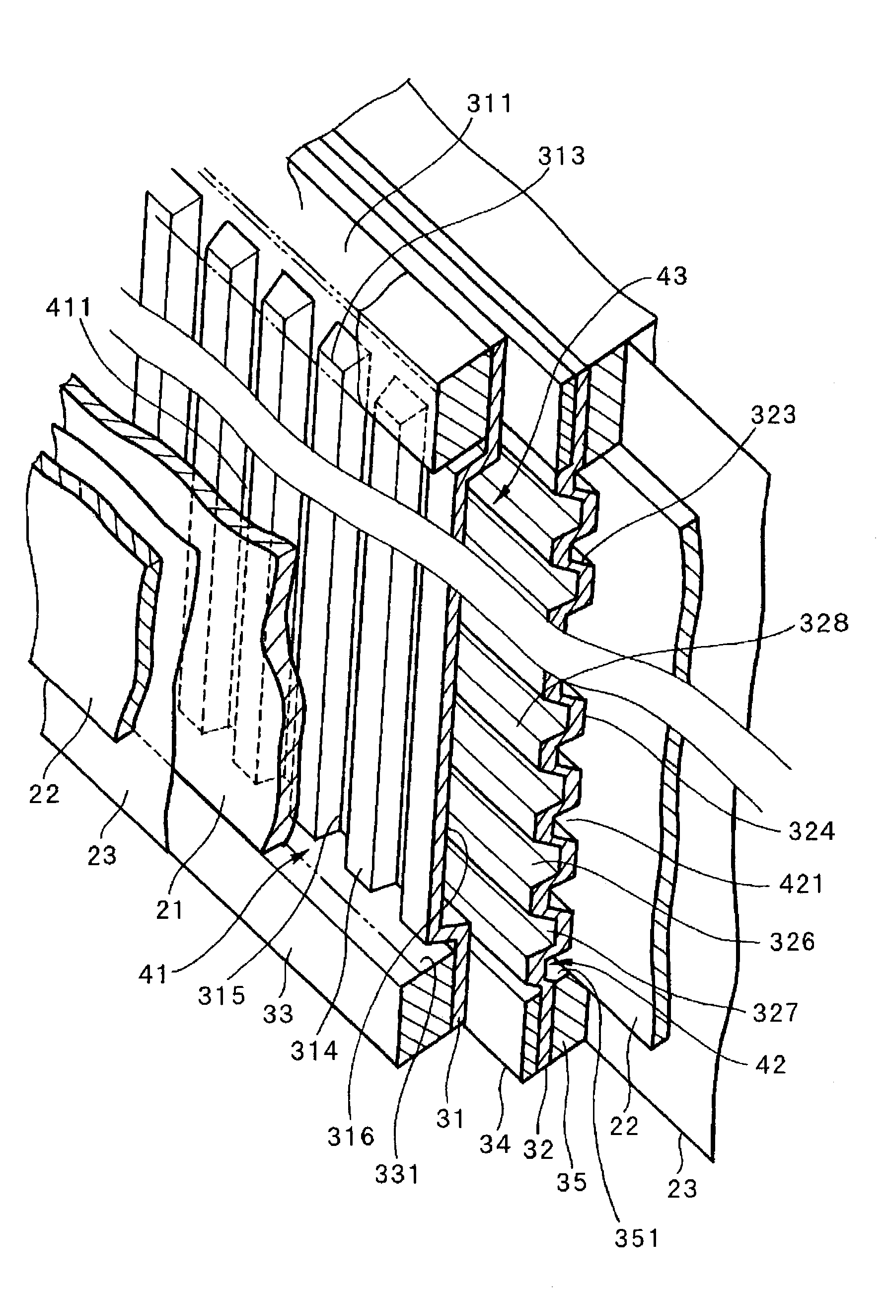
  • Fuel cell stack
  • Fuel cell stack
  • Fuel cell stack

Examples


first embodiment

[0077]Besides the above-described cooling system 13, such a structure that a heating means for heating the fuel cell stack 1 on starting the power generation may be employed. FIG. 11 is a schematic view showing a structure of the cooling system 13 in which a heater H is provided. The heater H is provided in the coolant supply pass 133 and located between the circulation pump 134 and the fuel cell stack 1. Since other structures are same as a first embodiment shown in FIG. 9, description thereof is omitted. The heater H operates to heat the coolant flowing in the coolant supply pass 133. The thus-heated coolant passes through the coolant-holding portions 43 that are provided on the respective separators 3 in the fuel cell stack 1, to thereby increase the temperature of the fuel cell stack 1.

[0078]Hereinafter, operation of the cooling system of the above-described second embodiment will be explained based on flow charts in FIG. 11 and FIG. 12. In this embodiment, when temperature of t...

second embodiment

[0081]As a method of firstly heating the fuel cell stack 1 with a heating means, such methods may be employed, in addition to a method of heating the coolant as in the second embodiment, as to provide a heating device directly heating a main body of the fuel cell stack 1 or to heat the air supplied from the air supply pass 110 with the heater 114 and pump it into the fuel cell stack 1. In such cases, it is preferable to perform heating after completing the processes in the steps S105 to S111 in advance and the coolant is taken out from the fuel cell stack 1. This allows high heating efficiency and also decreases energy consumption for heating since heat capacity of the fuel cell stack 1 is lessened.


PUM


Abstract

In starting power generation under low temperature conditions, an antifreeze liquid being coolant of a cooling system in a fuel cell stack is once recovered in a tank to reduce heat capacity of the fuel cell stack, and thereafter the power generation is started. Heat of reaction caused by the power generation restores the temperature to temperature under normal operation, and then the antifreeze liquid is again filled to drive the cooling system, so as to make it function as a cooler.

Description

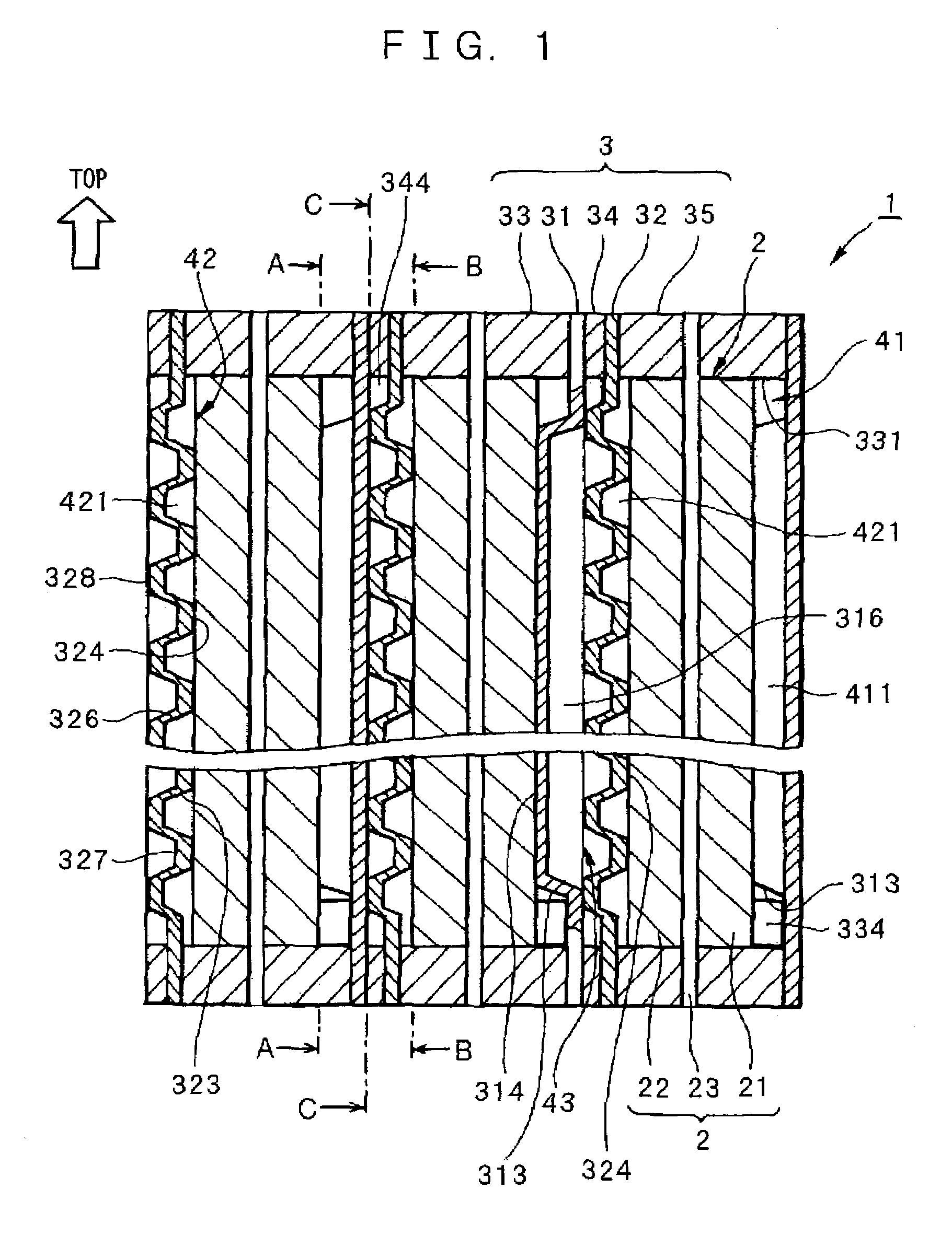
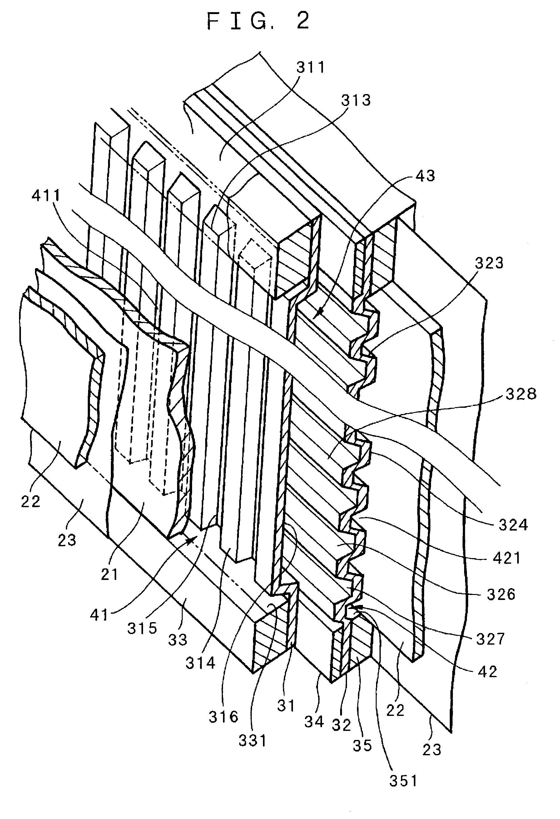
BACKGROUND OF THE INVENTION[0001]1. Field of the Invention[0002]The present invention relates to a fuel cell stack, particularly to facilitating its startup under freezing conditions.[0003]2. Description of Related Art[0004]Conventionally, a fuel cell generates heat of reaction and water in power generation. In a normal power generation state, a cooling device is provided therein to prevent the heat of reaction from raising the temperature of the fuel cell more than necessary. However, it is known that when starting the power generation under freezing conditions, the fuel cell is required to have a constant temperature, otherwise power generation efficiency drops off.[0005]This is because, under the freezing conditions, water generated by the power-generating reaction freezes on a surface of an electrode so as to prevent oxygen supply to the electrode. Such freezing of the generated water is caused by absorption of the heat of reaction produced by the power generation into a separat...

Claims


Application Information

Patent Timeline
IPC IPC(8): H01M8/04H01M2/14H01M8/02H01M8/10
CPCH01M8/04223H01M8/04268H01M8/0206H01M8/0267H01M8/04253Y02E60/50H01M2008/1095H01M2250/20Y02T90/32Y02T90/40H01M8/04225H01M8/2457H01M8/241H01M8/0258
Inventor SHIRAISHI, KOICHIANDO, MASAOHORIGUCHI, MUNEHISA
Owner EQUOS RES
Learn More