Hydraulic control device and pressure switch

a technology of hydraulic control device and pressure switch, which is applied in the direction of functional valve types, couplings, check valves, etc., can solve the problems of blockage of the discharge path to the reservoir, and achieve the effect of easy to tolera

Inactive Publication Date: 2010-10-21
HAWE HYDRAULIK SE
View PDF9 Cites 3 Cited by
  • Summary
  • Abstract
  • Description
  • Claims
  • Application Information

AI Technical Summary

Benefits of technology

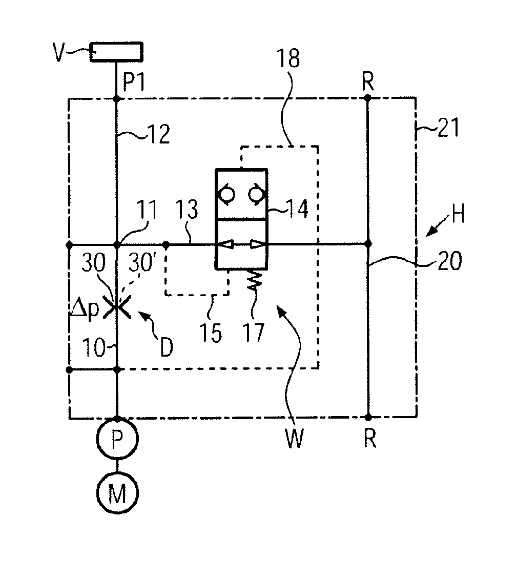
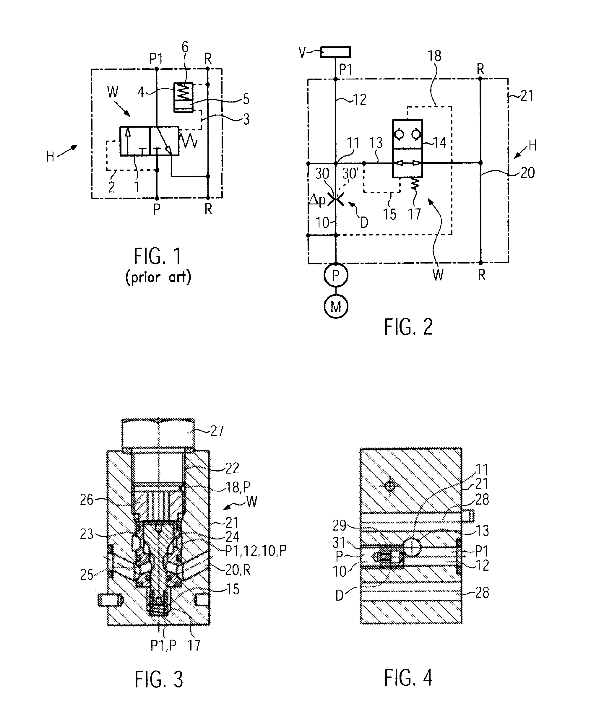
[0020]Expediently, the restrictor, the spring and the pressure receiving areas of the valve member are adapted in relation to each other such that when switching on the pressure source first a predetermined pressure drop across the restrictor or a predetermined flow rate through the restrictor is generated before still open the discharge path to the reservoir is blocked in leakage-free fashion. The build up of the pressure drop or the discharge flow rate occurs with a delay facilitating the start-up of a drive motor of the pressure source, preferably of a one phase alternating current electric motor. Due to this performance of the pressure switch and the restrictor a “gentle” response performance of the pressure switch is achieved without the necessity to provide further structural measures in the hydraulic control device for a similar function. When the drive motor of the pressure source is switched off, both residual pressure from the valve assembly and the pressure acting in the main channel from the side of the pressure source are relieved into the reservoir. Optionally, the pressure at the valve assembly may be held by use of a check valve blocking in flow direction to the reservoir in a part of the main channel, meaning that only the part of the main flow path will be pressure relieved which extends from this check valve to the pressure switch.
[0021]In small aggregates containing a small discharge flow rate pressure source used for generating high system pressure, the restrictor only causes a negligible counter pressure or a low pressure drop when the drive motor starts. First when about three quarters of the maximum pump discharge flow rate is reached the pressure drop will be large enough (about 5 to 10 bars) such that only then the multi-way seat valve constituting the pressure switch will switch into the blocking position. Then the pressure source supplies hydraulic medium through the restrictor to the valve assembly. Then the restrictor only causes a negligible pressure loss of a few percent which can easily be tolerated.

Problems solved by technology

This means that the discharge path to the reservoir becomes blocked after a delay but remains open during the start-up phase of the drive motor.

Method used


Image

  • Hydraulic control device and pressure switch
  • Hydraulic control device and pressure switch
  • Hydraulic control device and pressure switch

Examples


Embodiment Construction

[0028]A hydraulic control device H (FIG. 1—prior art) comprises a 3 / 2-multi-way slider valve 1 located between a pressure source P and a not shown valve assembly (pressure P1 acting at the valve assembly). The control member of the 3 / 2-multi-way slider valve 1 connects in pressure-free condition (first control position of the valve member, as shown) of the hydraulic control device H a line containing pressure P1 with a reservoir R, while a line to which the pressure source P is connected is blocked. This control position of the control member is assisted by a spring. The control member of the 3 / 2-multi-way slider valve 1 is actuated by a pilot pressure in a direction to a second control position. The pilot pressure originates from the pressure source P and acts in a pilot line 2. The control member is actuated parallel to the spring in the direction to the first control position by pilot pressure originating from the pressure P1 in a pilot line 3. The control member is formed as a s...


PUM


Abstract

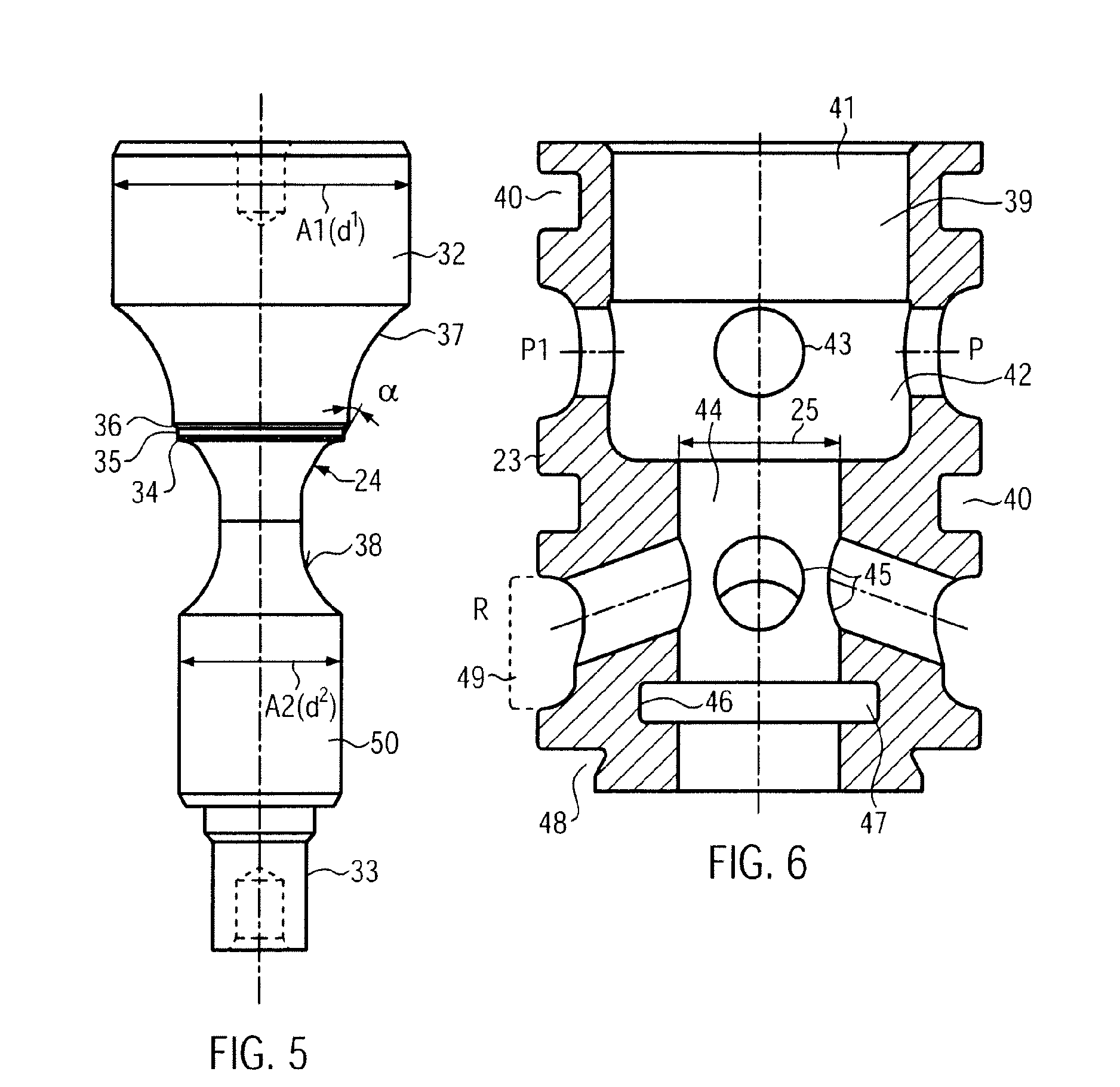
In a hydraulic control device H comprising a pressure source P which can be switched on and switched off, a reservoir R and a pressure switch W located in a discharge path 13 from a valve assembly V to the reservoir R, which pressure switch W either connects the valve assembly V with the reservoir R or blocks the valve assembly V versus the reservoir R, the pressure switch W contains a displaceable control member 16 which is actuated in a first switching direction by a spring 17 and a pilot pressure originating from the pressure P1 acting at the valve assembly V and in a second switching direction to a control position blocking the discharge path 13 by a pilot pressure originating from the supply pressure of the pressure source, the pressure switch W is designed as a 2/2-multi-way seat valve 16 operating with a blocking position without leakage. A valve member 24 forms the control member 16 and co-operates with a valve seat 25 arranged in the discharge path 13. The pressure source P and the valve assembly V are permanently connected via a main channel 10, 11 containing a restrictor D. The discharge path 13 branches off from the main channel 10, 11, 12 between the valve assembly V and the restrictor D. The pilot pressure actuating the valve member 26 in the switching direction towards the valve seat 25 originates from the supply pressure taken between the pressure source P and the restrictor D.

Description

BACKGROUND OF THE INVENTION[0001]The invention relates to a hydraulic control device according to the preamble of claim 1 and a to a pressure switch according to the preamble of claim 15.[0002]Hydraulic control devices containing a pressure switch are known in practice in various embodiments. In one embodiment (FIG. 1—prior art) the pressure switch is located within a main flow path between the pressure source and the valve assembly. The pressure switch is a 3 / 2-way slider valve and connects in one control position the pressure source with the valve assembly and separates the valve assembly from the reservoir. In the other control position the connection to the pressure source is blocked and the valve assembly is connected with the reservoir. In order to achieve a smooth movability of the control member of the slider valve the control member needs a slide fit which causes unavoidable and undesirable leakage losses in flow direction to the reservoir. These leakage losses are detrimen...

Claims


Application Information

Patent Timeline
Patent Type & Authority Applications(United States)
IPC IPC(8): F15B13/04F16K15/00
CPCF15B11/055F15B13/026F15B2211/45F15B2211/41572F15B2211/40553Y10T137/7904
Inventor NEUMAIR, GEORGKONIG, JOHANN
Owner HAWE HYDRAULIK SE
Why Eureka
Try Eureka