Chip antenna mounting apparatus

a technology of mounting apparatus and antenna, which is applied in the direction of antenna details, electrical equipment, and rod antennas, can solve the problems of unreliable connection, large empty space on the circuit board of pifa, and inability to meet current trends, etc., and achieves the effect of reducing empty space, stable support and small volum

Inactive Publication Date: 2007-12-18
CHANT SINCERE CO LTD
View PDF2 Cites 6 Cited by
  • Summary
  • Abstract
  • Description
  • Claims
  • Application Information

AI Technical Summary

Benefits of technology

[0010]It is therefore an objective of the present invention to provide a stable support for a chip antenna mounting apparatus to connect a chip antenna and a circuit board to form a required antenna radiation pattern, and reduce empty space on the circuit board to further achieve smaller volume when connecting the chip antenna on the circuit board.
[0012]The other objectives of the present invention are to provide a connection apparatus on a circuit board to connect a chip antenna and to reduce the empty space required for the chip antenna. The connection apparatus utilizes a coupling effect between the circuit board and a ground area and adjusts the angle between the chip antenna and the surface of the connection base to achieve the required radiation pattern.

Problems solved by technology

The traditional antenna, for example, rod antenna, yagi antenna and dish antenna, cannot satisfy the current trends which require low cost and compliance with the requirements of light, thin, short and with small volume.
However, there are many factors that need to be taken into consideration in the manufacturing process (for example, the defects causes by the solder skip and dry joint etc).
Further, the soldering method is difficult to solder the chip antenna vertical to the circuit board and it lacks stable support which results in an unreliable connection.
However, the PIFA still requires a large empty space on the circuit board.

Method used


Image

  • Chip antenna mounting apparatus
  • Chip antenna mounting apparatus
  • Chip antenna mounting apparatus

Examples


Embodiment Construction

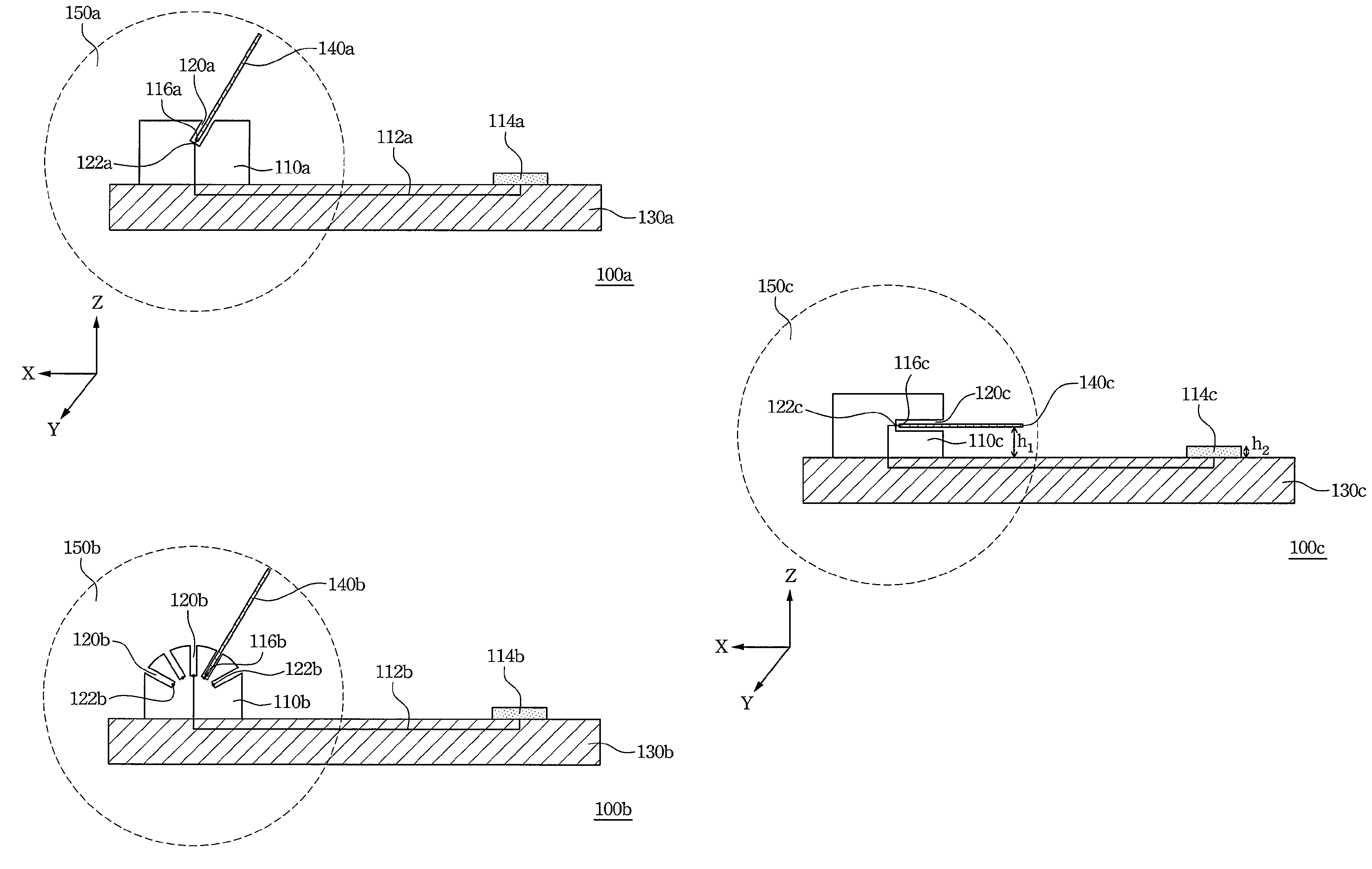
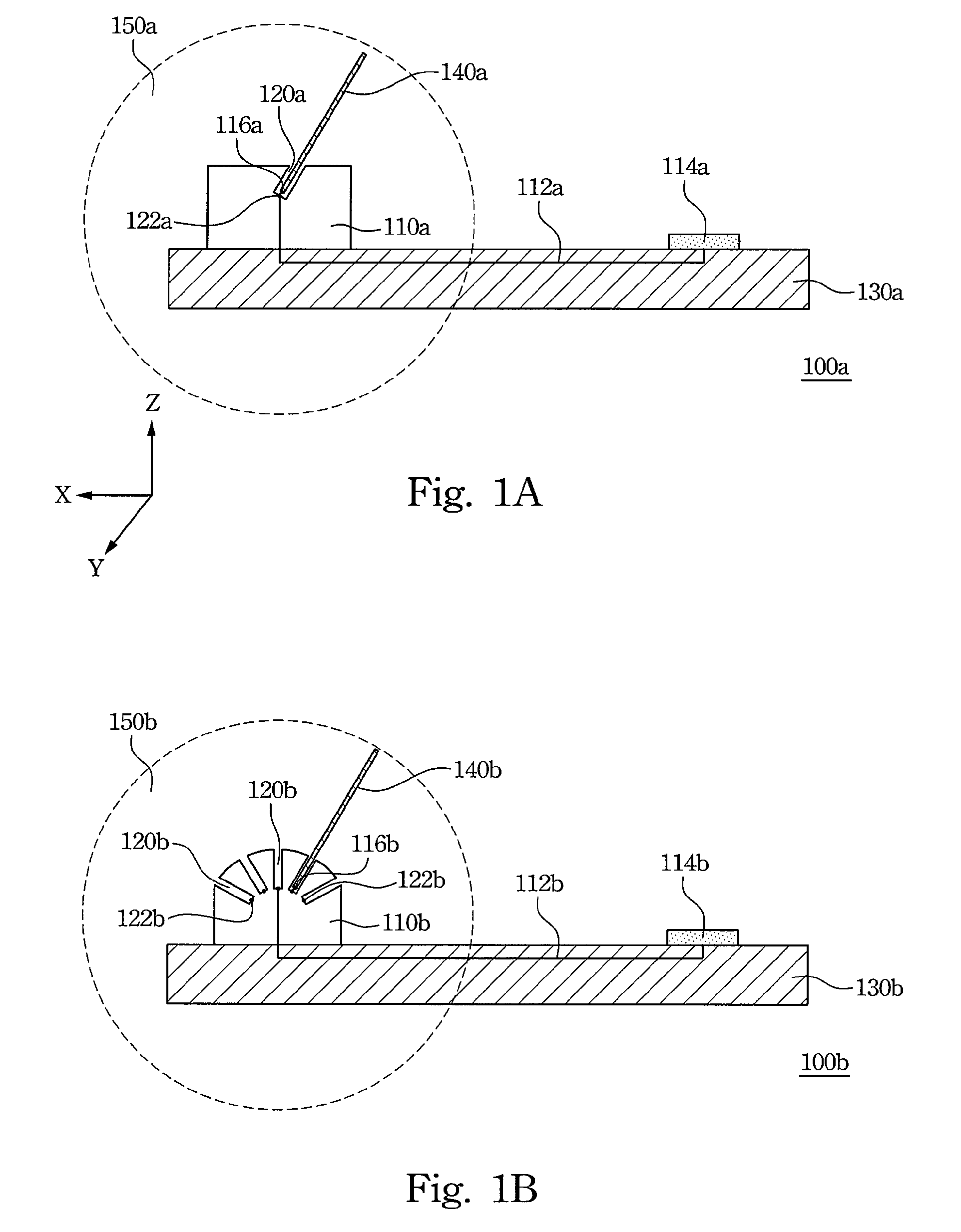
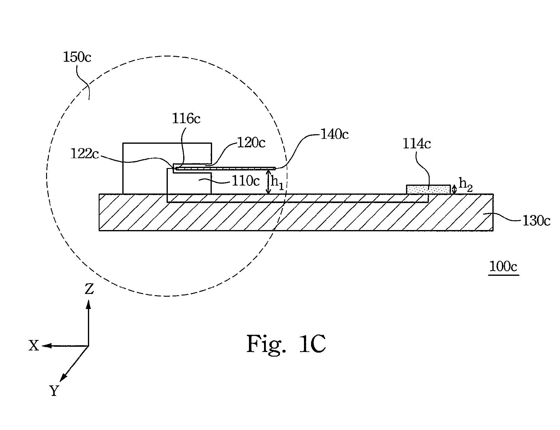
[0026]FIG. 1A illustrates a lateral view of a chip antenna mounting apparatus 150a of one preferred embodiment for the present invention. The chip antenna mounting apparatus 150a includes a connection base 110a, a connection wire 112a and at least a chip slot 120a. The connection base 110a is disposed on a circuit board 130a. The connection base 110a includes a connection wire 112a to connect the electronic components 114a of the circuit board 130a. At least one chip slot 120a is disposed on the connection base 110a to insert the chip antenna 140a. The chip antenna 140a is connected to the electronic components 114a of the circuit board 130a via the connection wire 112a.

[0027]In addition, the chip slot 120a has a connection point 122a to connect a feed-in point 116a of the chip antenna 140a for signal transmission. Generally, the feed-in point 116a of the chip antenna 140a may be a signal terminal of the chip antenna 140a or any part of the chip antenna 140a for signal transmission...


PUM


Abstract

A connection apparatus for a chip antenna includes a connection base and at least one chip slot. The connection base is disposed on a circuit board and connects to the electronic components of the circuit board via a connection wire. The chip slot is disposed on the connection base for inserting the chip antenna. Thus, the chip antenna is connected to the electronic components of the circuit board via the connection wire.

Description

RELATED APPLICATIONS[0001]The present application is based on, and claims priority from, Taiwan Application Serial Number 95105666, filed Feb. 20, 2006, the disclosure of which is hereby incorporated by reference herein in its entirety.BACKGROUND[0002]1. Field of Invention[0003]The present invention relates to a chip antenna mounting apparatus. More particularly, the present invention relates to an apparatus that provides a connection to a chip antenna on a circuit board.[0004]2. Description of Related Art[0005]There is rapid growth in the wireless communication sector, for example, cell phones, computer and Wi-Fi network, which utilize the wireless communication to transmit and receive signals. Wireless communication uses a signal transceiver and a signal transceiver antenna transmit and receive signals. The traditional antenna, for example, rod antenna, yagi antenna and dish antenna, cannot satisfy the current trends which require low cost and compliance with the requirements of l...

Claims


Application Information

Patent Timeline
Patent Type & Authority Patents(United States)
IPC IPC(8): H01Q1/24
CPCH01Q1/243H01Q1/125
Inventor HU, CHUAN-LINCHEN, YU-WEILIAO, CHANG-LUNLIN, SHUN-TIANYANG, CHANG-FACHEN, YEN-MINGWANG, CHAO-WEI
Owner CHANT SINCERE CO LTD
Why Eureka
Try Eureka