Pulling cord winding apparatus for window shades

a technology for winding apparatuses and window shades, which is applied in the direction of door/window protective devices, building components, construction, etc., can solve the problems of troublesome installation, troublesome pulling cord c, and difficulty in anchored cord c on a desired location, etc., to achieve easy installation, reduce the force, and reduce the thickness

Inactive Publication Date: 2007-12-25
CHENG LI MING
View PDF7 Cites 17 Cited by
  • Summary
  • Abstract
  • Description
  • Claims
  • Application Information

AI Technical Summary

Benefits of technology

[0004]In view of the aforesaid disadvantages occurred to the conventional winding devices that cannot be anchored on a desired location during extension and retraction, and are bulky and costly, the primary object of the present invention is to provide a pulling cord winding apparatus for window shades that is lighter and has a smaller thickness to reduce the force exerted on the spring in the pulling cord winding apparatus. The invention is compact and may be easily installed on the bottom rail of the window shade.
[0008]Still another object of the invention is to manage the pulling cords through the arched pressing plates, cord pressing members, and cord clamping members so that the pulling cords are retracted in a tidy manner without entangling or forming knobs, and the two elastic coils can retract the pulling cords without slipping at the maximum force.

Problems solved by technology

The rope usually is exposed outside and could cause a hazardous condition by tangling or strangling children playing nearby.
Hence the pulling cord C is difficult to be anchored on a desired location.
The aforesaid pulling cord winding device A not only is troublesome during operation, but also cannot anchor the window shade on a desired location during extension and retraction.
Moreover, the pulling cord winding device A consists of many elements, and is too bulky.
A bigger bottom rail B1 is needed to hold the pulling cord winding device A. In short, the entire device takes too much space and is too costly.
This shortens the service life of the device.

Method used


Image

  • Pulling cord winding apparatus for window shades
  • Pulling cord winding apparatus for window shades
  • Pulling cord winding apparatus for window shades

Examples


Embodiment Construction

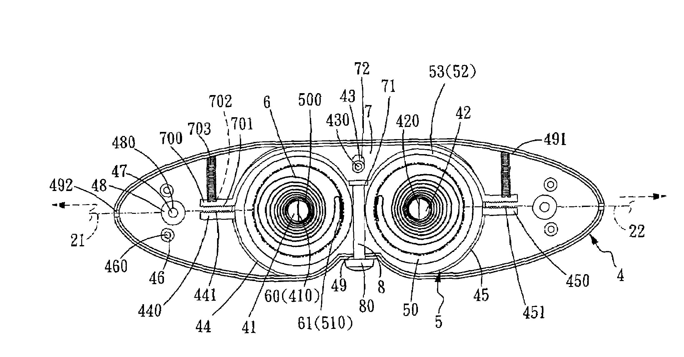
[0020]Please refer to FIGS. 3 and 4 for the basic structure of the pulling cord winding apparatus according to the present invention. The pulling cord winding apparatus 1 is installed on the bottom end of a bottom rail 20 of a window shade 2 to wind and house pulling cords 21 and 22 on two sides of the window shade 2. The pulling cord winding apparatus 1 includes an upper cap 3 and a lower seat 4 that are coupled together, two elastic take-up reels 5 corresponding to two holding struts 41 and 42 located in a center housing compartment 40 of the lower seat 4, two elastic coils 6 having two latch ends 60 and 61 housed and latched in the elastic take-up reels 5, a brake member 7 coupled on a post 43 located on one side of the housing compartment 40, and a push rod 8 to push the brake member 7. The brake member 7 may be moved and escape to enable the two elastic take-up reels 5 to rotate and perform brake function. Thus the two elastic coils 6 are retracted or released to extend or retr...


PUM


Abstract

A pulling cord winding apparatus for window shades includes an upper cap, a lower seat, two elastic take-up reels, two elastic coils, a brake member, and a push rod. The brake member has two arched pressing plates on two sides extended outwards to form respectively a cord pressing member which has second teeth on one side to engage with first teeth formed on cord clamping members on two outer sides of the housing compartment. When pushing the push rod, the brake member is moved and escapes to enable the two elastic take-up reels to rotate and brake. Through the arched pressing plates, cord pressing members and cord clamping members, pulling cords may be retracted smoothly without entangling or forming knobs. When the two elastic take-up reels retract the cords at the maximum force, the pulling cords do not slip, and the window shade may be extended and retracted as desired.

Description

FIELD OF THE INVENTION[0001]The present invention relates to a pulling cord winding apparatus for window shades that includes a push rod and a brake member that are movable and an arched pressing plate to prevent pulling cords from entangling or forming knobs during winding, and also has cord pressing members and cord clamping members to prevent two elastic coils from slipping at the maximum force during cords winding to extend and retract a window shade.BACKGROUND OF THE INVENTION[0002]A conventional window shade generally is lifted or lowered through a rope. The rope usually is exposed outside and could cause a hazardous condition by tangling or strangling children playing nearby. Hence for safety reason the rope of the window shade is generally collected in a winding device located on the bottom rail of the window shade without exposing to prevent risks.[0003]There are many types of pulling cord winding devices for window shades on the market. FIG. 1 illustrates one of the exampl...

Claims


Application Information

Patent Timeline
Patent Type & Authority Patents(United States)
IPC IPC(8): E06B9/322
CPCE06B9/322E06B2009/3225
Inventor CHENG, LI-MING
Owner CHENG LI MING
Why Eureka
Try Eureka