
Liquid crystal dispensing apparatus

a technology of liquid crystal dispensing and liquid crystal, which is applied in the direction of liquid transferring devices, instruments, transportation and packaging, etc., can solve the problems of increasing the time of liquid crystal fabrication process, increasing the consumption of liquid crystal, and reducing the efficiency of fabrication, so as to prevent the inferiority of liquid crystal from dropping, the effect of reducing the fabrication cost and being easy to fabrica

Inactive Publication Date: 2007-12-25
LG DISPLAY CO LTD
View PDF184 Cites 0 Cited by
  • Summary
  • Abstract
  • Description
  • Claims
  • Application Information

AI Technical Summary

Benefits of technology

[0019]Another object of the present invention is to provide a liquid crystal dispensing apparatus to be fabricated easily, to reduce the fabrication cost, and to prevent inferiority of liquid crystal dropping caused by a distortion of liquid crystal container, by forming the liquid crystal container using stainless steel having pressure endurance, and distortion resistance.
[0020]Still another object of the present invention is to provide a liquid crystal dispensing apparatus to prevent the liquid crystal from being contaminated by forming a fluorine resin film on inner part of a liquid crystal container.

Problems solved by technology

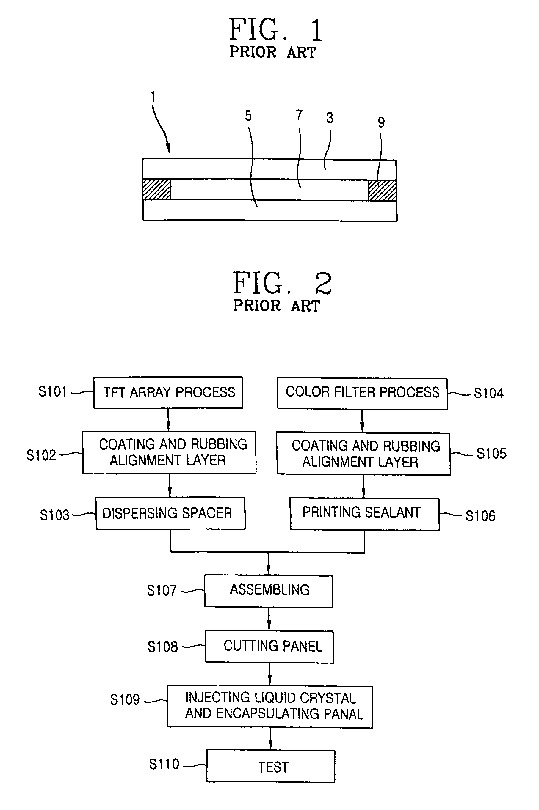
However, there are several some problems in the liquid crystal dipping injection method and / or vacuum injection method as follows.
For example, it takes about 8 hours to inject the liquid crystal completely in fabrication process of the 15 inches-liquid crystal display panel 15, the liquid crystal fabrication process time is increased due to the liquid crystal injection of long time, thereby decreasing fabricating efficiency.
Second, the liquid crystal consumption is increased in the above liquid crystal injection method.
On the other hand, when the liquid crystal is exposed to atmosphere or to a certain gas, the liquid crystal is contaminated by reaction with the gas.

Method used


Image

  • Liquid crystal dispensing apparatus
  • Liquid crystal dispensing apparatus
  • Liquid crystal dispensing apparatus

Examples


Embodiment Construction

[0036]Reference will now be made in detail to the preferred embodiments of the present invention, examples of which are illustrated in the accompanying drawings.

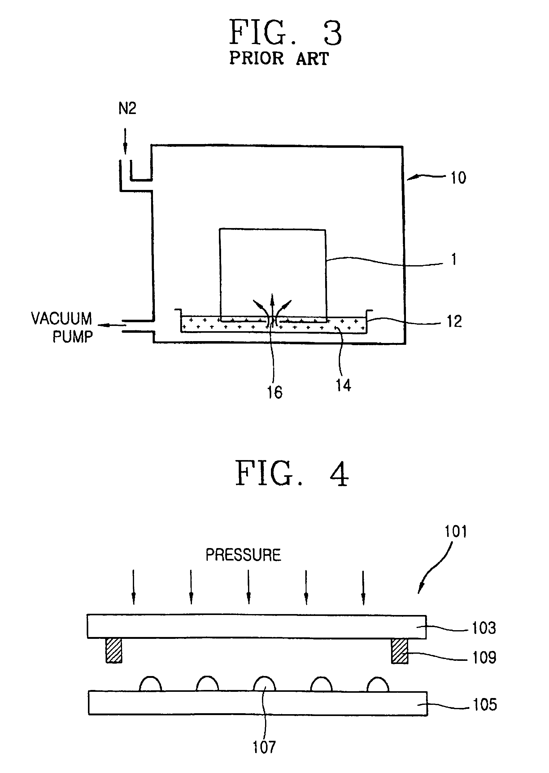
[0037]In order to solve the problems of the conventional liquid crystal injection methods such as a liquid crystal dipping method or liquid crystal vacuum injection method, a liquid crystal dropping method has been introduced recently. The liquid crystal dropping method is a method for forming a liquid crystal layer by directly dropping the liquid crystal onto the substrates and spreading the dropped liquid crystal over the entire panel by pressing together the substrates during the assembling process of the substrates, rather than by injecting the liquid crystal into the empty unit panel by the pressure difference between the inner and outer sides of the panel. According to the above liquid crystal dropping method, the liquid crystal is directly dropped onto the substrate in a short time period so that the liquid crystal la...


PUM

PropertyMeasurementUnit
gas pressureaaaaaaaaaa
magnetic fieldaaaaaaaaaa
magnetic forceaaaaaaaaaa

Abstract

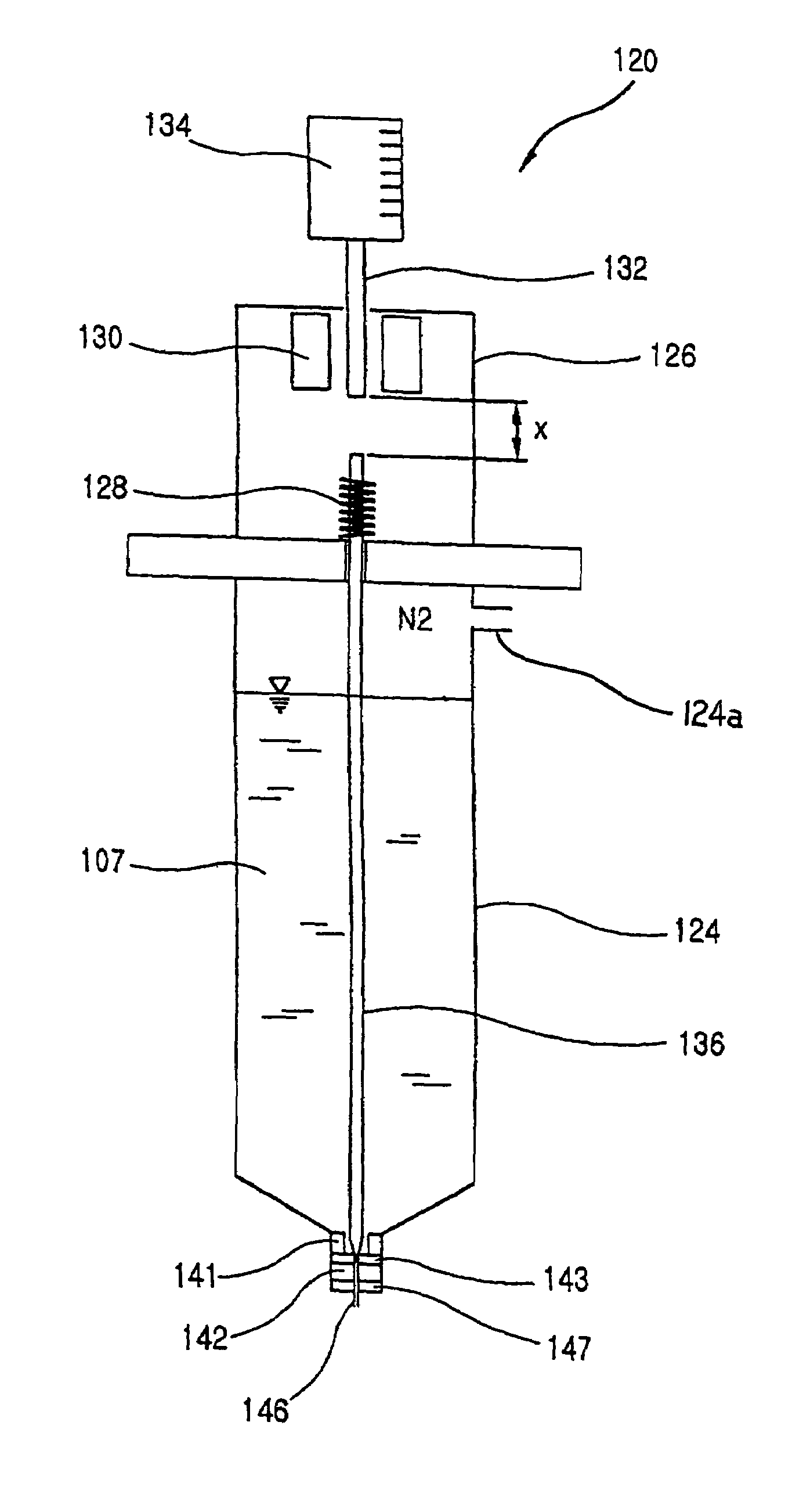
A liquid crystal dispensing apparatus for dispensing liquid crystal onto a substrate includes a liquid crystal container, a nozzle structure, and a valve structure. The liquid crystal container contains the liquid crystal to be dispensed. The nozzle structure is disposed at a lower portion of the liquid crystal container, and the liquid crystal is dispensed through the nozzle structure onto the substrate. The valve structure is disposed to control flow of the liquid crystal from the liquid crystal container to the nozzle structure in accordance with a gas pressure provided from a gas input of the liquid crystal container. The liquid crystal container may be formed of substantially entirely of metal. An inside surface of the liquid crystal container may include a fluorine resin.

Description

[0001]This is a continuation of application Ser. No. 10 / 128,233, filed on Apr. 24, 2002 now U.S. Pat. No. 6,824,023.[0002]The present application claims the benefit of Korean Patent Application Nos. 9122 / 2002 and 10617 / 2002 respectively filed in Korea on Feb. 20, 2002 and Feb. 27, 2002, both of which are hereby incorporated by reference.BACKGROUND OF THE INVENTION[0003]1. Field of the Invention[0004]The present invention relates to a liquid crystal dispensing apparatus, and particularly, to a liquid crystal dispensing apparatus that has a simple structure and that can drop liquid crystal at an exact position on a substrate.[0005]2. Discussion of the Related Art[0006]Recently, various portable electric devices such as mobile phones, personal digital assistants (PDA), and notebook computers have been developed, and therefore, needs for a flat panel display device for use in a small, light and power-efficient device are correspondingly increasing. To meet the needs, flat panel display ...

Claims


Application Information

Patent Timeline
Patent Type & Authority Patents(United States)
IPC IPC(8): B67D3/00B05C5/00B65D83/00G02F1/13G02F1/1333G02F1/1341
CPCB05C5/0212G02F1/1303B05C5/0225
Inventor KIM, WAN-SOOKWEON, HYUG-JINSON, HAE-JOON
Owner LG DISPLAY CO LTD
Learn More