Liquid crystal display device having good heat radiating function

a technology of liquid crystal display and heat radiating function, which is applied in the direction of instruments, non-linear optics, optics, etc., can solve the problems of difficult to obtain high brightness, the edge type backlight unit is not suitable for an lcd, and the difficulty of being applied to an lcd panel having a large area, etc., to achieve efficient light emission and increase the surface area

Active Publication Date: 2013-05-07
LG DISPLAY CO LTD
View PDF7 Cites 1 Cited by
  • Summary
  • Abstract
  • Description
  • Claims
  • Application Information

AI Technical Summary

Benefits of technology

[0014]Therefore, an object of the present invention is to provide a liquid crystal display (LCD) device capable of efficiently radiating light emitted from an optical source by forming heat radiating members such as grooves or protrusions which increase a surface area, on a lower cover, an upper cover, and a guide panel.
[0015]To achieve these and other advantages and in accordance with the purpose of the present invention, as embodied and broadly described herein, there is provided a liquid crystal display (LCD) device, comprising: an LCD panel; a plurality of optical sources disposed at one or more sides of a lower part of the LCD panel to supply light to the LCD panel; a light guide plate disposed below the LCD panel to guide the light emitted from the optical source to the LCD panel; a guide panel for supporting the LCD panel and the light guide plate; a lower cover and an upper cover for assembling the LCD panel, the light guide plate, and the guide panel; and heat radiating members formed in at least one of the guide panel, the lower cover, and the upper cover to increase surface areas of the guide panel, the lower cover, and the upper cover to radiate heat generated from the optical source.
[0018]The LCD device having a good radiating function according to the present invention may have the following advantages.
[0019]Since means for increasing a surface area, such as grooves, holes and convexed portions may be formed at the lower cover, or the upper covers, or the guide panel, light emitted from the optical sources may be efficiently radiated. This may prevent inferiority of the LCD device due to temperature increment of a backlight unit.

Problems solved by technology

However, the edge type backlight unit has a difficulty in being applied to an LCD panel having a large area since a lamp is installed on a side surface of an LCD panel.
Furthermore, since light is supplied through the light guide plate, it is difficult to obtain high brightness.
Accordingly, the edge type backlight unit is not suitable for an LCD panel for an LCD TV having a large area, one of the most spotlighted LCD panel.
However, the conventional LCD device has the following problems.
This temperature increment of the backlight unit causes deformation of the optical sheet, damage of a junction of the LED, decrement of optical efficiency of the LED, degradation of liquid crystal on the panel, thereby lowering reliability of main components of the LCD device.

Method used


Image

  • Liquid crystal display device having good heat radiating function
  • Liquid crystal display device having good heat radiating function
  • Liquid crystal display device having good heat radiating function

Examples


first embodiment

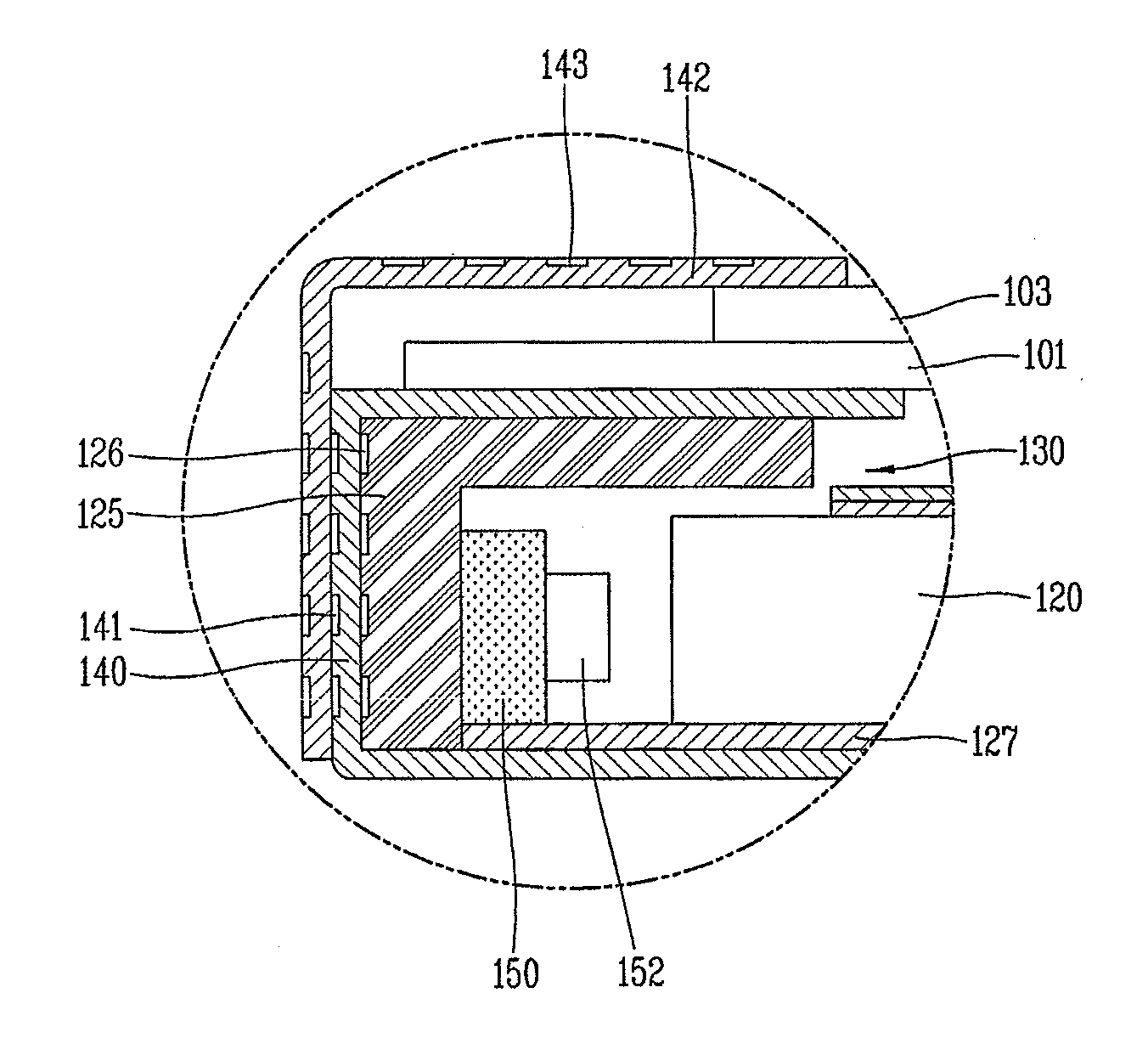
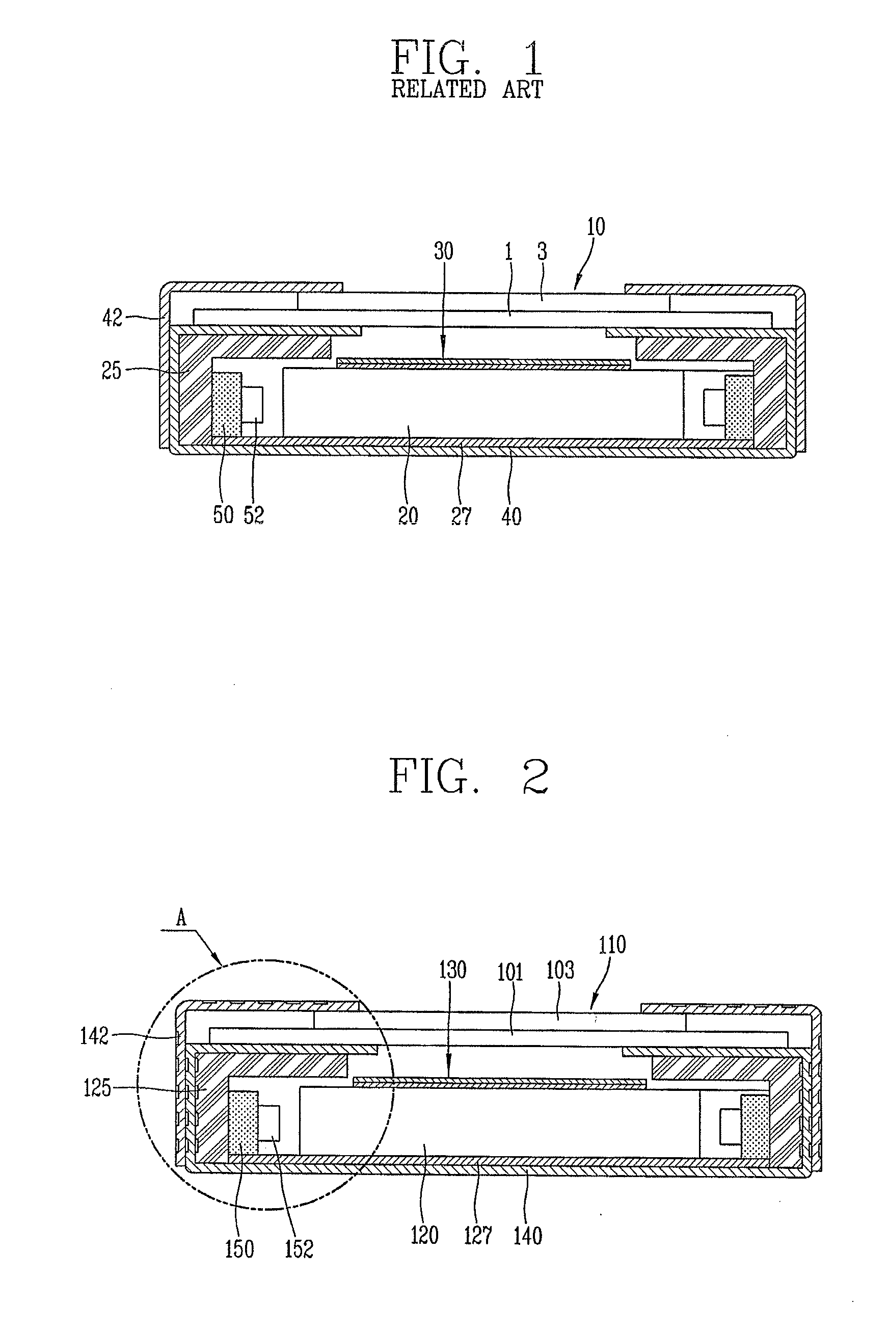
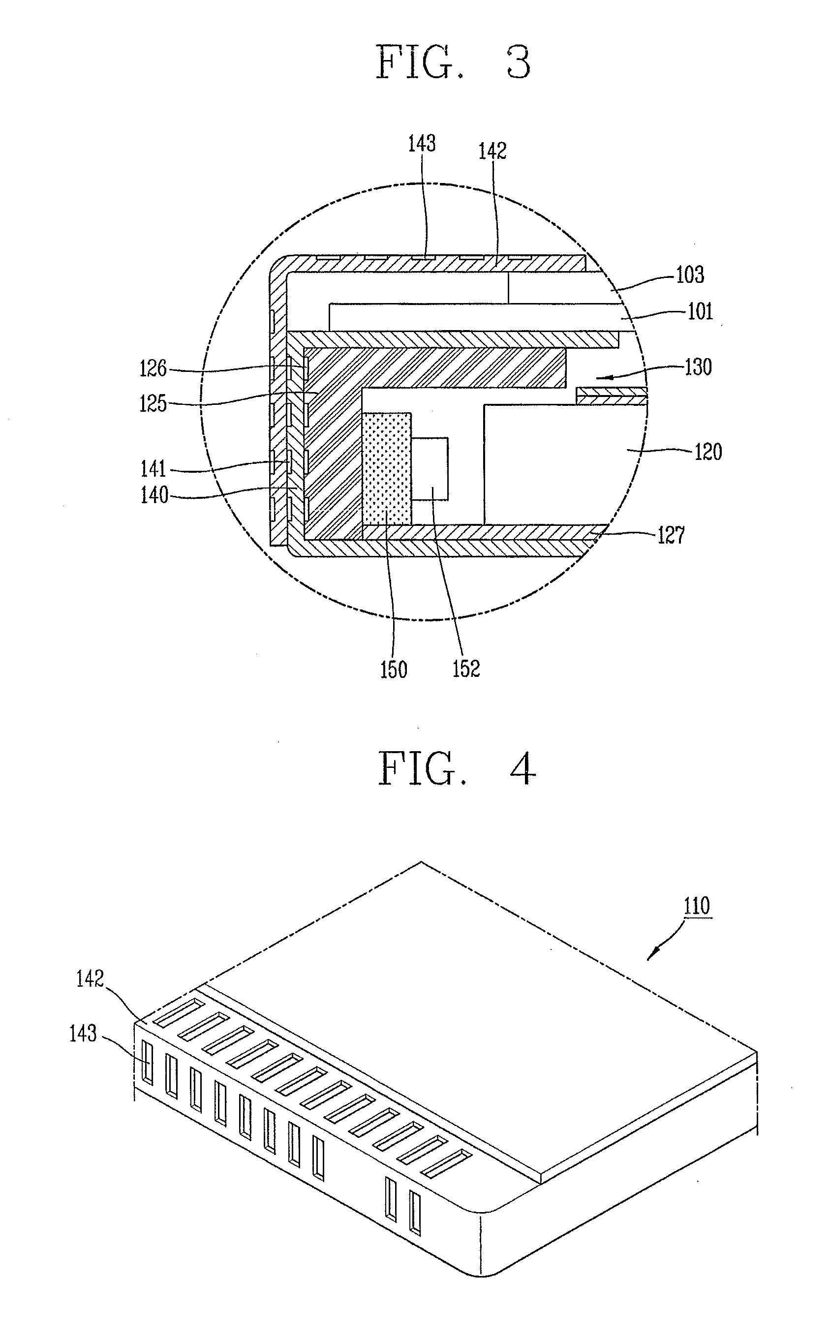
[0032]FIG. 2 is a view showing a structure of an LCD device according to the present invention.

[0033]As shown in FIG. 2, the LCD device comprises an LCD panel 110, and a backlight unit disposed below the LCD panel 110 for supplying light to the LCD panel 110.

[0034]The LCD panel 110 includes a first substrate 101, a second substrate 103, and an LC layer (not shown) disposed therebetween. The first substrate 101 is a thin film transistor (TFT) array substrate, and is provided with thin film transistors and pixel electrodes formed at a plurality of pixels defined by a plurality of gate lines and data lines. On the other hand, the second substrate 103 is a color filter substrate, and includes a black matrix, a color filter layer, and a common electrode. The black matrix is an image non-display region such as a TFT forming region and a gate / data lines forming region, and serves to prevent transmittance of light. The color filter layer is composed of sub color layers such as red, green an...

second embodiment

[0053]FIG. 5 is a partially enlarged view showing a structure of an LCD device according to the present invention.

[0054]The LCD device according to the second embodiment is same as the LCD device according to the first embodiment except for types of the grooves. Accordingly, only the different structure of the LCD device according to the second embodiment will be explained.

[0055]As shown in FIG. 5, a plurality of grooves 226 are formed on a side surface of a guide panel 225 contacting a lower cover 240 and an upper cover 242. And, a plurality of holes 241 and 243 are formed at the lower cover 240 and the upper cover 242. The holes 241 and 243 correspond to the grooves of the first embodiment, and serve to enhance a heat radiating function through the lower cover 240 and the upper cover 242.

[0056]More concretely, heat is transmitted to the lower cover 240 and the upper cover 242 through the guide panel 225. As a part of the guide panel 225 is directly exposed out of the LCD device by...

third embodiment

[0058]FIG. 6 is a partially enlarged view showing a structure of an LCD device according to the present invention.

[0059]As shown in FIG. 6, a plurality of grooves 326 are formed on side surfaces of a lower cover 340 and a guide panel 325. And, a plurality of convexed portions 343 are formed at an upper cover 342. Since the upper cover 342 has an increased surface area due to the convexed portions 343, heat can be efficiently radiated out through the lower cover 340 and the upper cover 342.

[0060]The shape of the convexed portions 343 is not limited to a specific one. The convexed portions 343 serve to enhance efficiency of heat radiation by increasing the surface area of the upper cover 342. Accordingly, the convexed portions 343 may be configured to have any shapes only if the efficiency of heat radiation can be enhanced by increasing the surface area of the upper cover 342. For instance, the convexed portions 343 may be formed to have a circular shape, or an oval shape, or a polygo...


PUM

PropertyMeasurementUnit
surface areasaaaaaaaaaa
heataaaaaaaaaa
sizeaaaaaaaaaa

Abstract

Disclosed is a liquid crystal display (LCD) device having a good heat radiating function. Surface areas of a lower cover, an upper cover, and a guide panel are increased by forming grooves at the lower cover, the upper cover, and the guide panel. Heat generated from an optical source is rapidly radiated through the lower cover, the upper cover, and the guide panel having increased surface areas. This may prevent temperature increment of a backlight unit.

Description

CROSS-REFERENCE TO A RELATED APPLICATION[0001]Pursuant to 35 U.S.C. §119(a), this application claims the benefit of earlier filing date and right of priority to Korean Application No. 10-2008-0134996, filed on Dec. 26, 2008, the content of which is incorporated by reference herein in its entirety.BACKGROUND OF THE INVENTION[0002]1. Field of the Invention[0003]The present invention relates to a liquid crystal display (LCD) device, and particularly, to an LCD device capable of efficiently radiating light emitted from an optical source by increasing surface areas of a lower cover, an upper cover, and a guide panel.[0004]2. Background of the Invention[0005]Recently, various portable electric devices, such as mobile phones, personal digital assistant (PDA), and note book computers have been developed, because of their small size, light weight, and power-efficient operations. Accordingly, flat panel display devices, such as liquid crystal displays (LCDs), plasma display panels (PDPs), fie...

Claims


Application Information

Patent Timeline
Patent Type & Authority Patents(United States)
IPC IPC(8): G02F1/1333
CPCG02F1/133385G02F1/133308G02F1/133615G02F2001/133314G02F2001/13332G02F2001/133628G02F2201/36G02F1/133314G02F1/13332G02F1/133628G02F1/1333G02F1/1335
Inventor LEE, YOUNG-BINKWAK, YOUNG-JAE
Owner LG DISPLAY CO LTD
Why Eureka
Try Eureka