
Cyclotron with beam phase selector

a cyclotron and beam technology, applied in the field of cyclotrons with beam phase selectors, can solve the problems of reducing the efficiency of beam retrieval, reducing the quality of retrieved beams, and producing inconvenien

Inactive Publication Date: 2008-01-01
PANASONIC CORP
View PDF22 Cites 3 Cited by
  • Summary
  • Abstract
  • Description
  • Claims
  • Application Information

AI Technical Summary

Benefits of technology

This design effectively narrows the phase width of beams, significantly improving beam permeability and achieving higher beam current, even with external ion sources, by converting phase differences into orbital differences and allowing for flexible adjustment to experimental conditions.

Problems solved by technology

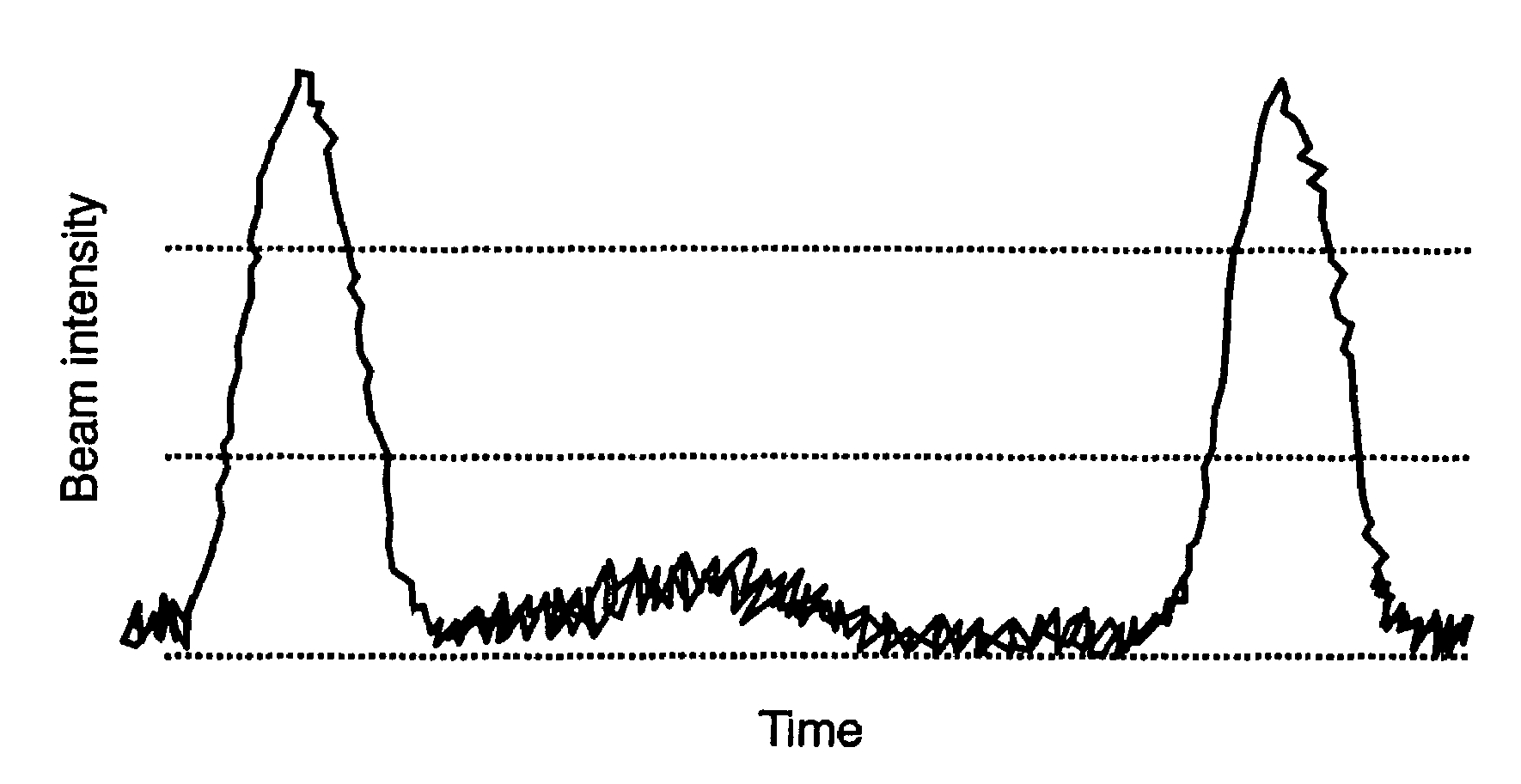
The variations in orbits lower the efficiency of retrieving beams, and the variations in energy degrade the quality of retrieved beam 5.
However, the aforementioned phase slit produces an inconvenience in a cyclotron employing an external ion source; disposing conventional phase slits, such as phase slits 6 and 14, lowers beam permeability to approx.
1 / 50, and therefore weakens beam current.
The problem probably comes from the difference in incidence energy of particles to be fed into the cyclotron.
Therefore, the conventional beam control method—where the control of phase widths is relied on the difference in orbits caused by the difference in energy gained by a particle at the gap—is not effective in blocking out undesired particles.

Method used


Image

  • Cyclotron with beam phase selector
  • Cyclotron with beam phase selector
  • Cyclotron with beam phase selector

Examples


Embodiment Construction

Exemplary Embodiment

[0030]Hereinafter will be described how the acceleration voltage applying section of the present invention works in accordance with the principle of operation.

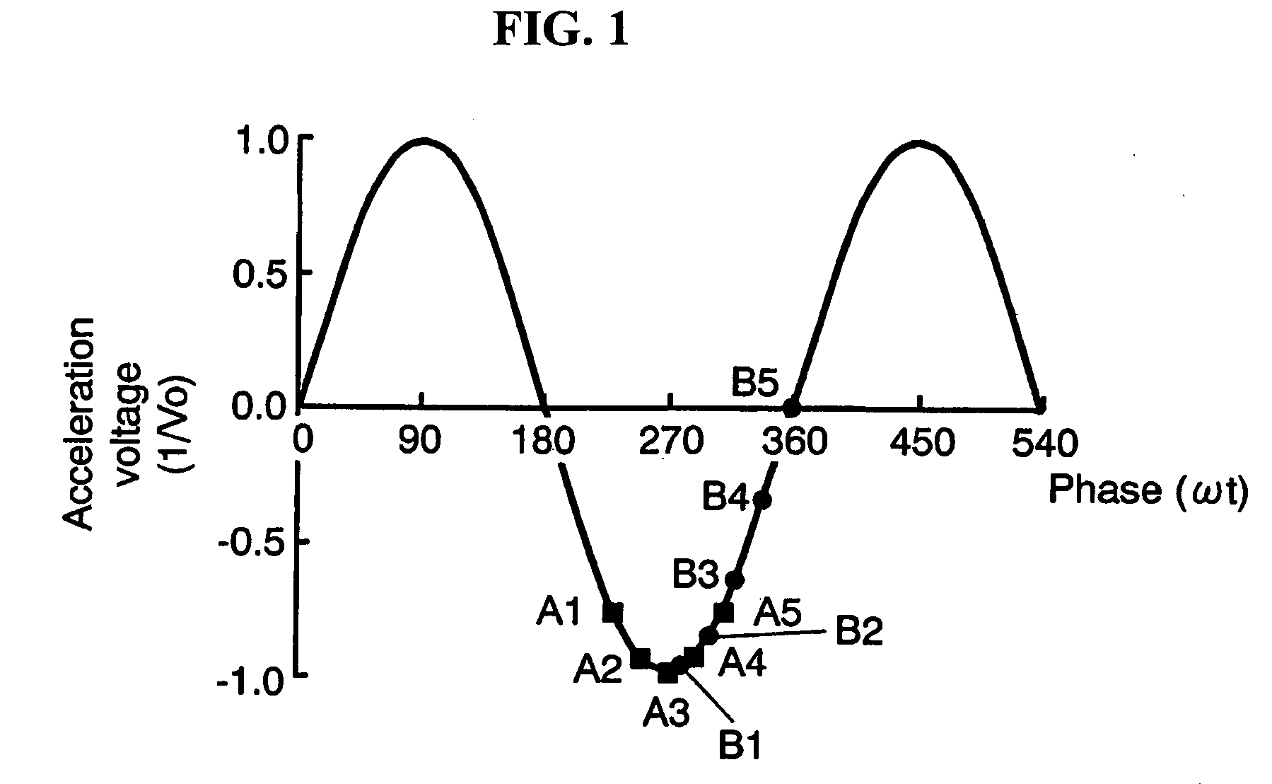
[0031]FIG. 1 shows an RF acceleration voltage applied to a beam with a time lag at an acceleration voltage applying section of the present invention. When particles pass across gap 2, acceleration voltage is applied to the particles at positions A1 through A5. This is the same as that of the conventional example (FIG. 12) described earlier in Background Art. In addition to the application of the voltage, the acceleration voltage applying section of the present invention further applies an RF acceleration voltage having a phase different from those applied at positions A1 through A5. For example, position Bn of FIG. 1 has a phase shift of 50° from position An.

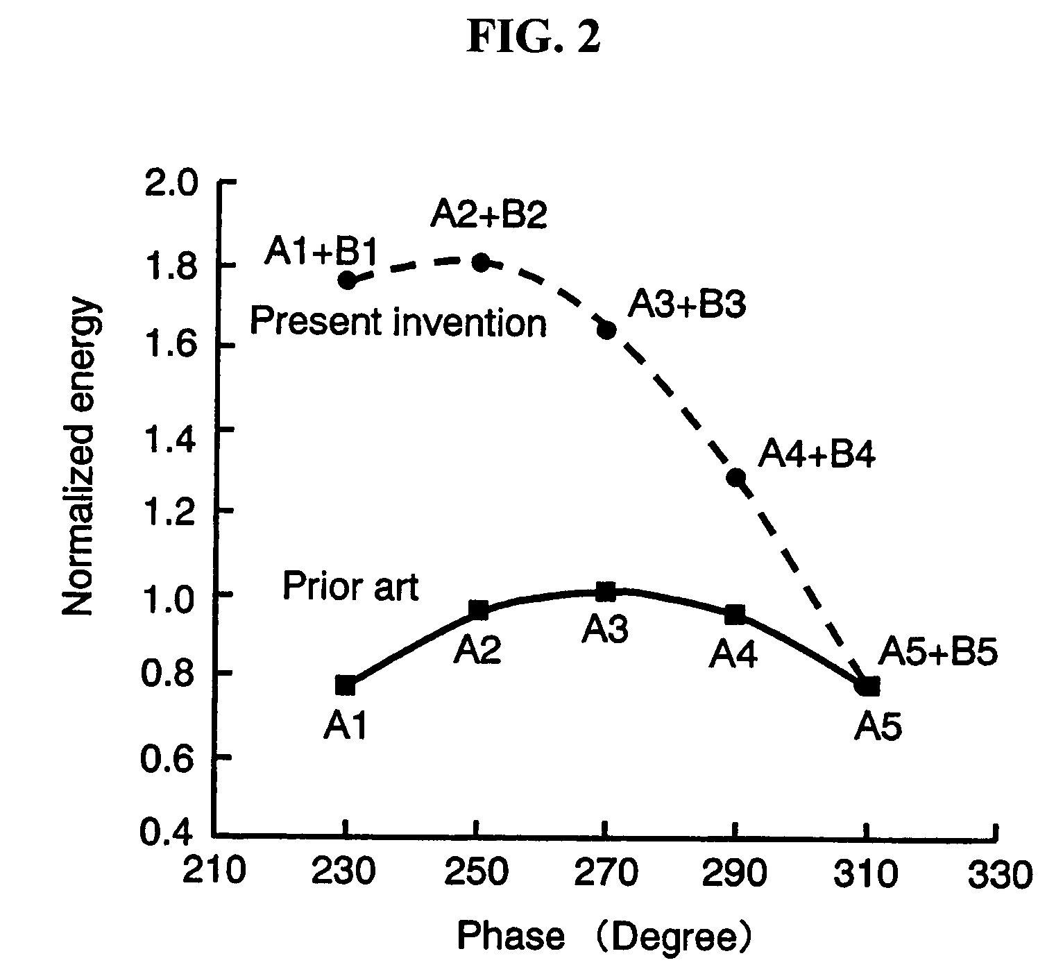
[0032]FIG. 2 shows total energy gained by each particle accelerated at points A1 through A5. According to the present invention, each particle is accel...


PUM


Abstract

Disclosed here is a cyclotron having a beam phase selector capable of controlling phase widths of beams and improving beam permeability for increasing beam current. The cyclotron contains an acceleration voltage applying section and a beam blocking section, at least any one of the two sections has a movable structure. While a particle is passing across a gap between dee electrodes, the acceleration voltage applying section applies RF acceleration voltage to the particle, and further applies RF acceleration voltage having a phase different from the phase of previously applied RF acceleration voltage. The beam blocking section blocks undesired particles. Preferably, the acceleration voltage applying section at least has an electrode having an opening in a direction of the core of the cyclotron. Also preferably, operations on phase-width control can be performed outside the cyclotron, with vacuum condition in the cyclotron maintained.

Description

FIELD OF THE INVENTION[0001]The present invention relates to a cyclotron having a beam phase selector for effectively controlling phase widths of beams.BACKGROUND ART[0002]FIG. 11 shows how particles are accelerated in a cyclotron. A cyclotron is typically formed of an electromagnet and dee electrodes 1. The whole structure of dee electrode 1 is accommodated in an evacuated box. Accelerated particles including protons are generated in an ion source located at cyclotron core 3. The ion source located in an evacuated box is often called an internal ion source. On the other hand, there is another type of cyclotron, where the ion source is disposed outside the cyclotron and beams are conveyed from the ion source to cyclotron core 3. The structure has an advantage of being accessible to the ion source in maintenance work, with the vacuum condition of the evacuated box maintained. Such an ion source disposed outside the evacuated box is called an external ion source. In a cyclotron having...

Claims


Application Information

Patent Timeline
Patent Type & Authority Patents(United States)
IPC IPC(8): H05H13/00
CPCH05H13/00
Inventor SASAKI, YUICHIROHATANAKA, KICHIJI
Owner PANASONIC CORP
Learn More