X-ray imaging apparatus and its control method

a control method and x-ray technology, applied in the field of x-ray imaging technique, can solve the problems of poor time-setting precision, gantry becomes bulky, and the worst case of mismatch from the start to the end of scanning

Inactive Publication Date: 2008-01-01
CANON KK
View PDF18 Cites 156 Cited by
  • Summary
  • Abstract
  • Description
  • Claims
  • Application Information

AI Technical Summary

Problems solved by technology

For this reason, the actual measurement start time is indefinite and typically does not coincide with a time planned for starting measurement, resulting in poor time-setting precision.
For example, full scanning typically assumes that a mismatch from the start to the end of scanning is the worst case possible.
(1) The gantry becomes bulky, and cannot be carried into a room in the case of a recumbent position CT which is currently distributed. Since a large centrifugal force is generated upon rotation, a high-speed imaging system cannot be adopted.
(2) When a type that rotates a subject (subject rotation type) is adopted, the scan time ranges from 5 to 10 sec / rotation.

Method used


Image

  • X-ray imaging apparatus and its control method
  • X-ray imaging apparatus and its control method
  • X-ray imaging apparatus and its control method

Examples


Embodiment Construction

[0021]The preferred embodiments of the present invention will now be described in detail in accordance with the accompanying drawings.

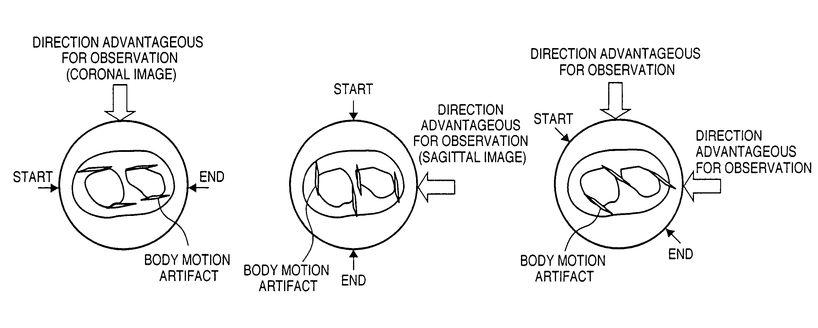
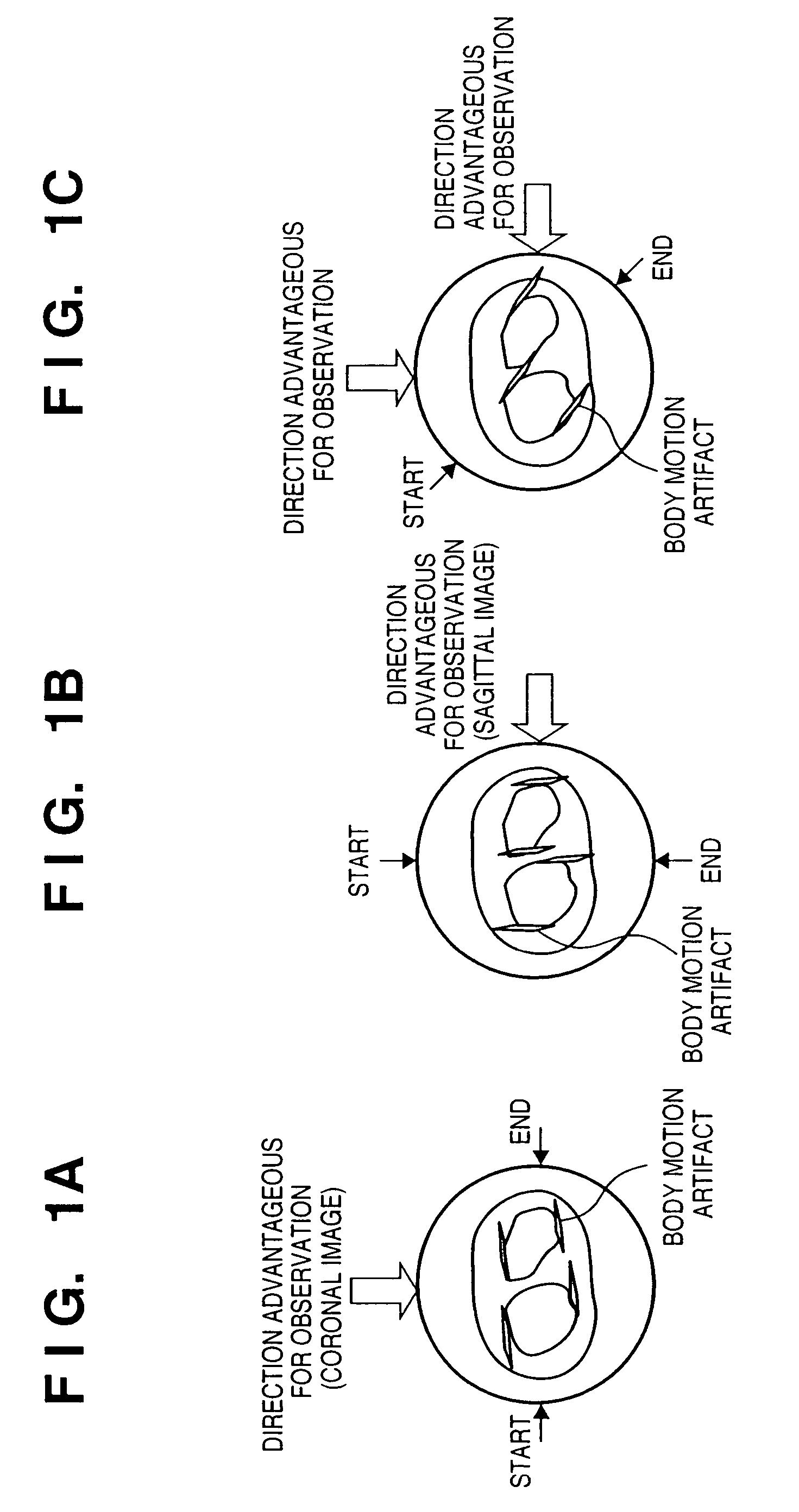
[0022]FIGS. 1A to 1C are views for explaining the concept of an embodiment of the present invention. FIGS. 1A to 1C show a chest axial image, a data acquisition start position (START) and end position (END) in half-scanning (180°+fan angle), and a suitable observation direction associated with a tomosynthesis which is reconstructed from data obtained by half-scanning, and is parallel to the body axis. When body motion has occurred in a half-scan, a data mismatch in the START and END directions becomes conspicuous, and linear artifacts are generated in a direction parallel to a line that connects the START and END positions. Taking FIG. 1A as an example, linear artifacts that run in the lateral direction are generated. In the case of FIG. 1B, linear artifacts that run in the up-and-down direction (in the drawing figure) are generated. Also, in the case...


PUM

PropertyMeasurementUnit
angle detectoraaaaaaaaaa

Abstract

In an X-ray imaging apparatus, which has a radiation source for generating radiation, and a detector for detecting the amount of radiation of the radiation, a subject is relatively rotated with respect to radiation which is radiated from the radiation source in the direction of the detector, and radiation amount data for image reconstruction is acquired in a predetermined rotation section. At this time, a desired observation direction perpendicular to the rotation axis in association with the subject is designated, and the position of the predetermined rotation section is determined on the basis of the designated observation direction.

Description

FIELD OF THE INVENTION[0001]The present invention relates to an X-ray imaging technique for imaging a radiation distribution in a subject using radiation such as an X-ray CT apparatus for sensing an image using radiation such as X-rays or the like.BACKGROUND OF THE INVENTION[0002]Conventionally, an X-ray CT apparatus which irradiates a subject with X-rays, detects X-rays transmitted through or scattered by the subject using an X-ray detector, and forms a fluoroscopic image, tomosynthesis, or three-dimensional (3D) image on the basis of this X-ray detection output (the number of photons of X-rays) is known. As such X-ray CT apparatus, a cone beam CT apparatus has been developed. In a normal X-ray CT apparatus, an X-ray beam is limited in the Z-direction, and is called a fan beam. However, cone beam CT (CBCT) uses an X-ray beam which also spreads in the Z-direction, and for this reason is called a cone beam.[0003]In CT, a half-scanning technique that scans through “180°+fan angle” is ...

Claims


Application Information

Patent Timeline
Patent Type & Authority Patents(United States)
IPC IPC(8): G01N23/00G01T1/00A61B6/00A61B6/03G03B42/02G06T1/00
CPCA61B6/025A61B6/032A61B6/04A61B6/4085A61B6/502A61B6/54A61B6/00
Inventor TSUJII, OSAMU
Owner CANON KK
Why Eureka
Try Eureka