Self-retracting utility knife

a utility knife and self-retracting technology, applied in the field of utility knives, can solve the problems of difficult to remove a spare blade, cumbersome grasping, and the blades can fall out, and achieve the effect of narrowing the handl

Active Publication Date: 2008-01-08
BLACK & DECKER INC
View PDF71 Cites 90 Cited by
  • Summary
  • Abstract
  • Description
  • Claims
  • Application Information

AI Technical Summary

Benefits of technology

[0013]One advantage of the present invention is that a single non-indexed actuator can be used to both move the blade carrier and blade between retracted and fully extended positions, as well as between retracted and less than fully extended positions corresponding to the extension of a typical box cutter. As a result, the utility knives of the present invention avoid the need for reliance on accurate finger pressure to ensure that the blade maintains an extension corresponding to extension of a box cutter.
[0014]Another advantage of a currently preferred embodiment of the present invention is that a spare blade holder is incorporated in the housing that allows retention of the blade via the cutting edge and back edge clipped in engagement with the spare blade holder as opposed to clipping opposite surfaces defining the body of each blade. In this manner, the spare blades are oriented obliquely relative to the cutting blade, thus allowing for a narrower handle.

Problems solved by technology

Unfortunately, upon opening the handle, the spare blades can fall out and become separated from the handle.
In addition, it can be difficult to remove a spare blade from the opposing clip members because of the force required to remove it from the grasp of the opposing clip members, and because there is very little of the spare blade exposed rendering it cumbersome to grasp.
Further, the number of spare blades that may be stored in such a holder is limited because each additional spare blade increases the thickness of the stacked spare blades, forces the opposing clip members further apart, and correspondingly increases the force applied to the blades by the opposing clip members.
The increased force applied by the opposing clip members makes it difficult to add or remove a spare blade from the holder.
When the blade is constantly exposed, consequent risks of injury to people or objects nearby are possible while the knife is not in use.
However, such prior art utility knives do not permit one to limit the extension of the blade as in an indexed blade carrier design, other than by only partially depressing the operating actuator, which can be awkward.
As a result, it can be difficult to maintain a constant extension of the blade.
For example, it can be difficult to maintain a constant extension of the blade having the blade extend just enough to penetrate the box to cut therethrough, while also avoiding extension of the blade to an extent that might cause the blade tip to cut through material contained in the box.

Method used


Image

  • Self-retracting utility knife
  • Self-retracting utility knife
  • Self-retracting utility knife

Examples


Embodiment Construction

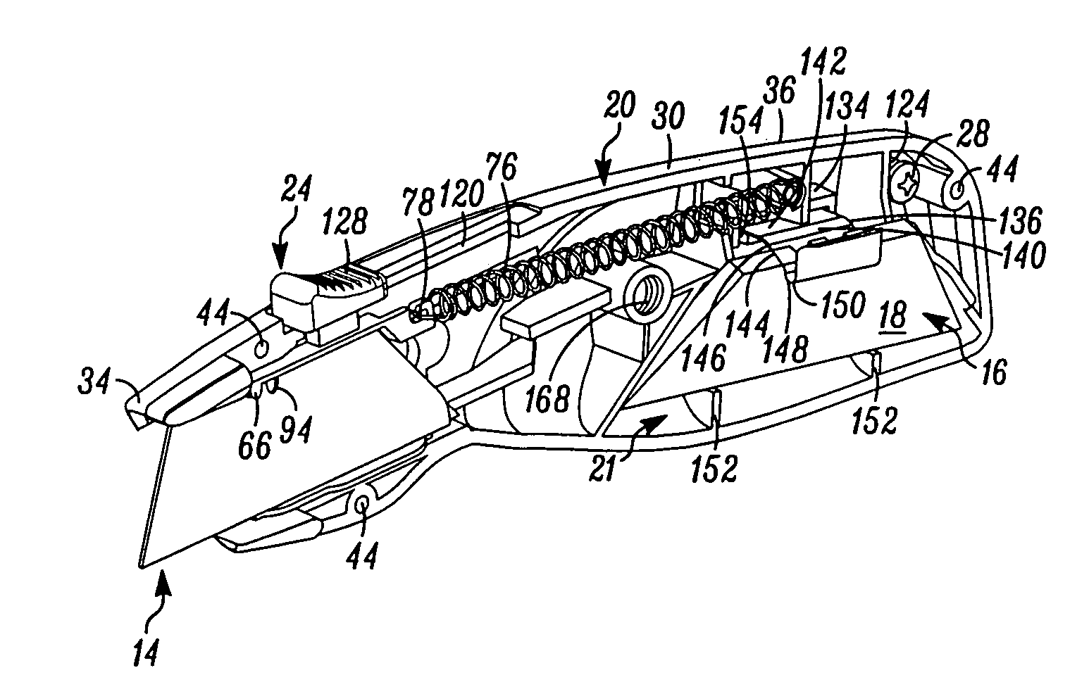
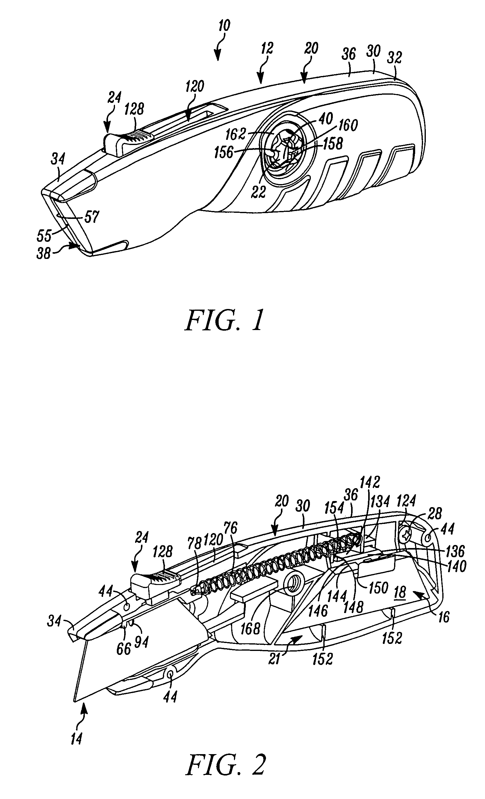
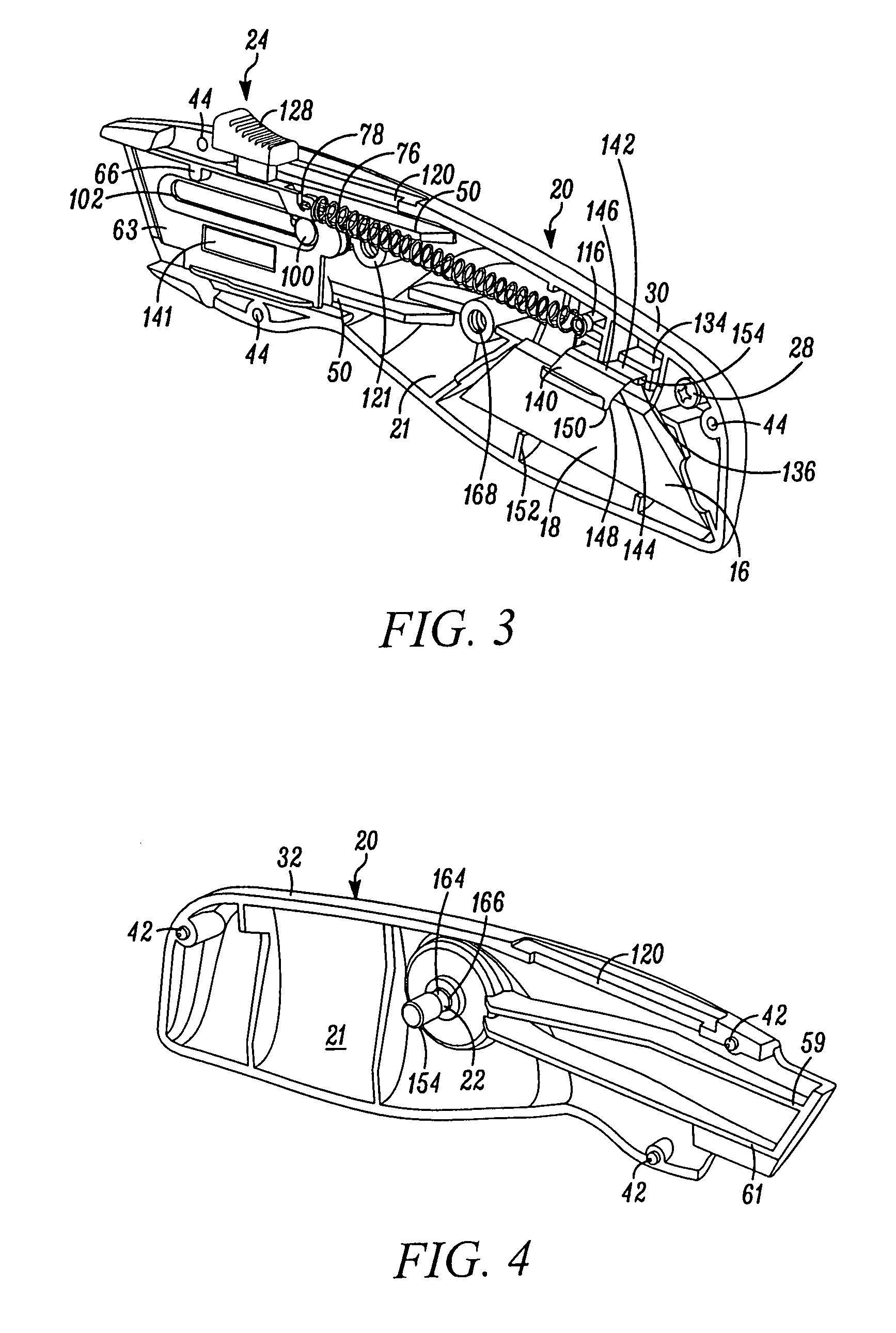
[0027]In FIG. 1, a utility knife embodying the present invention is indicated generally by the reference numeral 10. The utility knife 10 includes a handle 12, a blade 14 (FIGS. 2 and 5-8) and a spare blade holder assembly 16 for storing spare blades 18 (FIGS. 2, 3, and 5-8). The handle 12 includes a housing 20 defining a substantially internal cavity 21 (FIGS. 2-4), a mechanism 22 for releasably holding opposing portions of the housing 20 together, and an actuator 24 for moving the blade 14 between retracted and extended positions, and for releasing the blade 14 from the housing 20.

[0028]As shown in FIGS. 2, 3, and 6-10, a blade carrier 26 supports thereon the blade 14 and is movably mounted within the housing 20 to move the blade between a retracted position with the blade received or concealed within the housing, and at least one, and preferably a plurality of, non-indexed extended positions with the cutting edge of the blade extending outwardly of the housing. As shown in FIGS. ...


PUM


Abstract

A utility knife includes a housing and a blade carrier movably mounted to the housing. The blade carrier includes a blade supporting surface for supporting a blade, wherein the blade carrier is movable between a retracted position with at least a substantial portion of the blade retracted in the housing, and a first extended position with at least a portion of the blade extending outwardly of the housing. An actuator is operably connected to the blade carrier and is operable to move the blade carrier between the retracted and extended positions to, in turn, move a blade located on the blade carrier between the retracted and extended positions. A biasing member biases the blade carrier toward the retracted position. A stop member is movable between a first position and a second position. In the first position, the stop member is engagable with the blade carrier to thereby limit extension of the blade carrier and blade located thereon to a second extended position spaced inwardly on the housing relative to the first extended position. In the second position of the stop member, the stop member is spaced away from the blade carrier to thereby permit movement of the blade carrier and blade located thereon to the first extended position.

Description

FIELD OF THE INVENTION[0001]The present invention relates to utility knives, and more particularly, to a utility knife that includes a blade carrier for selectively moving a utility knife blade between retracted and extended positions. The utility knife blade is normally retracted, and extends to a cutting position only when an operating actuator is manipulated and automatically returns to the retracted position upon release of the operating actuator.BACKGROUND INFORMATION[0002]Utility knives generally include a handle and at least one replaceable blade. Because such blades are known to become worn or damaged, utility knife handles generally include provisions to allow a blade to be removed from the handle, so that the blade may be reversed in the handle (in order to provide a new cutting edge for the knife) and / or replaced by another blade. In addition, utility knife handles generally include a blade carrier for supporting the blade and an actuator operably connected to the blade c...

Claims


Application Information

Patent Timeline
Patent Type & Authority Patents(United States)
IPC IPC(8): B26B1/08
CPCB26B5/001B26B5/003
Inventor GREEN, MATTHEW C.
Owner BLACK & DECKER INC
Why Eureka
Try Eureka