
Adjustable bracket assembly for shelf-mounted electronic display device

Inactive Publication Date: 2008-01-08
MICRO INDS CORP
View PDF4 Cites 44 Cited by
  • Summary
  • Abstract
  • Description
  • Claims
  • Application Information

AI Technical Summary

Benefits of technology

[0008]Therefore, from the foregoing, it can be understood that what is desirable is a mounting device that can be used to attach an electronic display device to shelving of various size. The adjustable bracket assembly of the present invention fulfills this desire. The adjustable bracket assembly of the present invention allows an electronic display to be easily attached to shelving having a considerably different depth, as well as a different height. The adjustable bracket assembly also facilitates the removal or relocation of an electronic display device, and acts to strengthen and stabilize shelving constructed of weak materials.
[0009]While retail store shelving may be of varying size, it has been determined that there is at least one feature common to each size—a series of holes that reside near the rear of the top surface thereof. In addition, the different sizes of shelving generally fall within a range of depths and thicknesses. The adjustable bracket assembly of the present invention makes use of these shelving features to allow the bracket assembly to be easily but securely affixed to a wide variety of shelving.
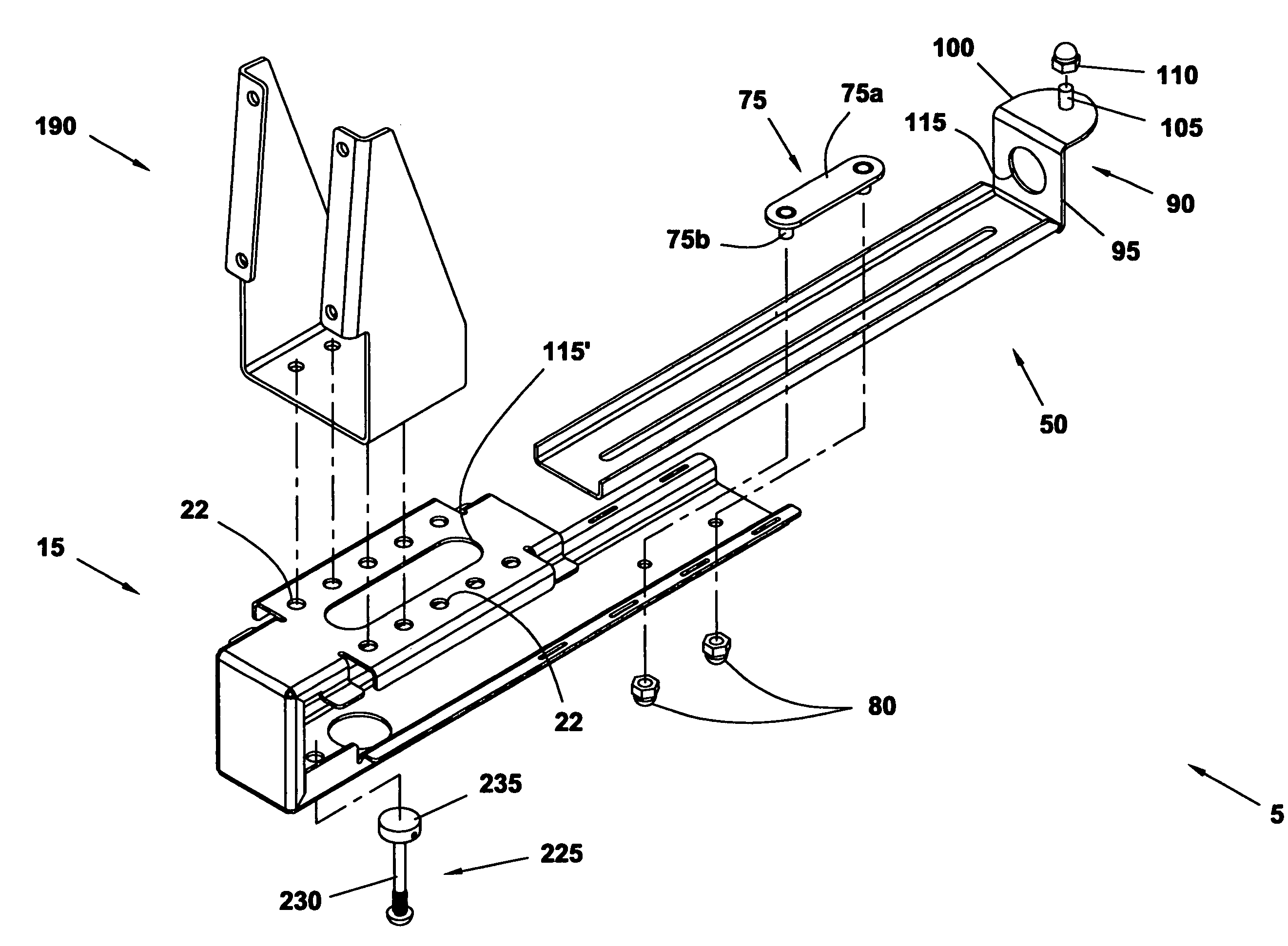
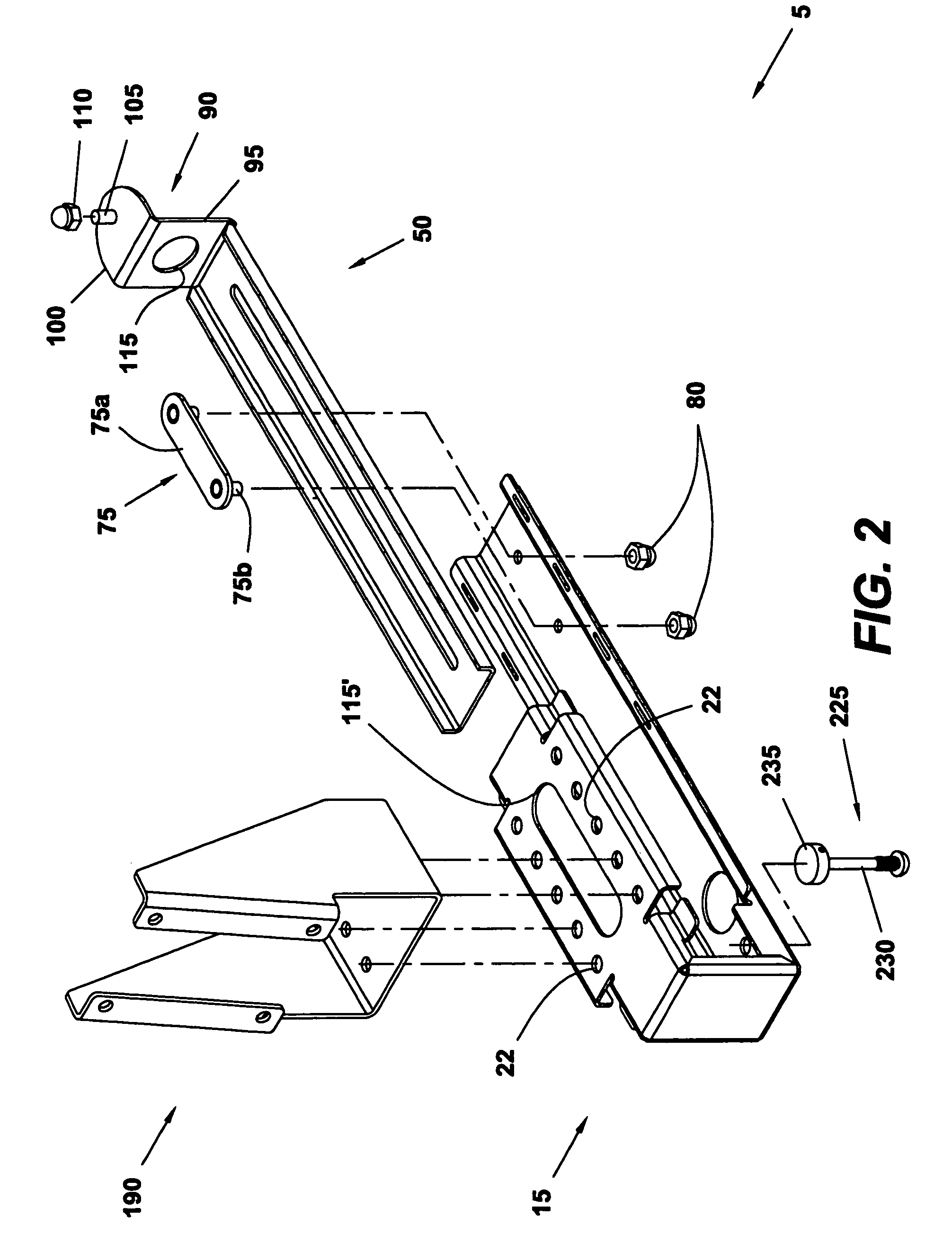
[0010]The adjustable bracket assembly preferably includes a substantially C-shaped front bracket arranged in a sliding relationship with a rear bracket having an upwardly extending portion. The brackets may be slidably displaced and secured in position to accommodate shelving of different depth. The C-shaped front bracket is provided with ample spacing between a bottom leg and a top surface leg thereof to also accommodate shelving of different height. The shape of the front bracket allows it to trap a portion of the shelf to which it is installed. One or more fasteners or similar devices may be used to releasably secure the position of the front bracket to the shelf. The position of the rear bracket is preferably secured by passing a threaded fastener through one of the aforementioned holes in the shelf, and thereafter securing the bracket to the shelf with a like-threaded nut.
[0014]The design of the adjustable bracket assembly not only makes it easy to install an electronic display to a shelf, it also allows use of the shelf space behind the area of the electronic display device. More specifically, because only the top leg of the C-shaped front bracket resides above the top surface of the shelf when installed thereto, a majority of the shelf space behind the electronic display will still be available for displaying products. Additionally, because provisions are preferably made for allowing power and communication cables to be routed through a portion of the adjustable bracket assembly residing beneath the shelf, no additional space is occupied thereby. Thus, the adjustable bracket assembly of the present invention provides for an easy, adaptable, and space conserving means of securely mounting an electronic display device to a shelf.

Problems solved by technology

Therefore, the amount of information that may be provided via these electronic displays is virtually endless.
However, it has been discovered that retail store shelving is of varying size, without any particular set of standards.
Consequently, a mounting device developed to attach an electronic display device to one specific type / size of shelving may not work to mount the display device to shelving of a different type / size.
This is problematic for several reasons.
Thus, a single retail establishment employing these electronic displays would be forced to maintain a supply of dissimilar mounting devices.
Aside from issues of varying shelf size, it has also been found that display shelving is often constructed or rather thin materials.
As a result, such shelves may not exhibit a desirable amount of stability subsequent to the attachment of an electronic display device thereto.
This situation may be especially problematic when employing electronic display devices incorporating touch screens, for example, as the interaction between a customer and the display device may put additional stress on the shelf to which the display device is mounted.

Method used


Image

  • Adjustable bracket assembly for shelf-mounted electronic display device
  • Adjustable bracket assembly for shelf-mounted electronic display device
  • Adjustable bracket assembly for shelf-mounted electronic display device

Examples


Embodiment Construction

)

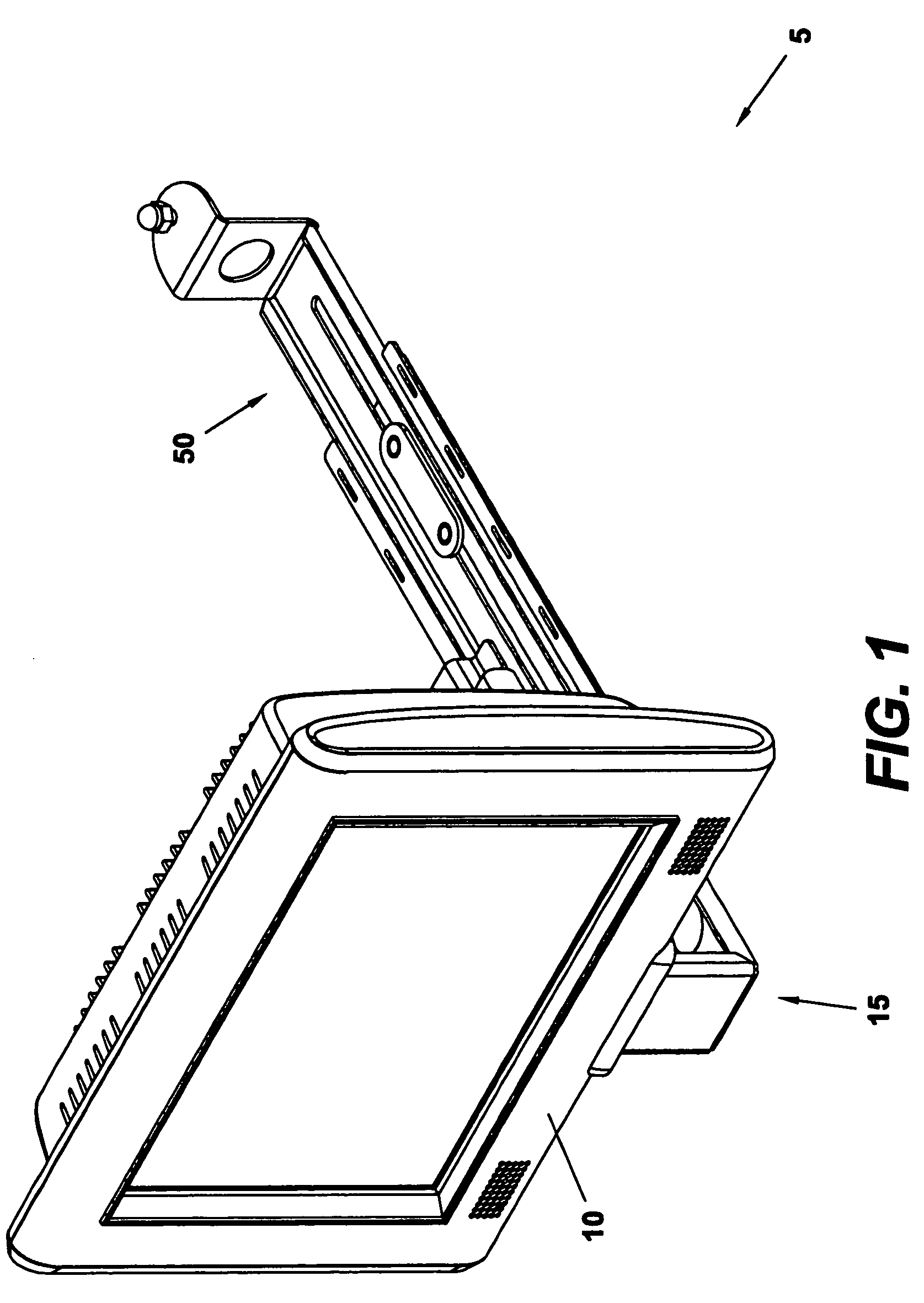
[0032]One exemplary embodiment of an assembled adjustable bracket assembly 5 of the present invention can be seen in FIG. 1 with an electronic display device 10 attached thereto. In this particular embodiment, the electronic display device 10 is a mini computer having an integrated display. However, it should also be realized that the electronic display device 10 could simply be a monitor connected to a remote computer, or another similar device.

[0033]As can be observed in FIGS. 1-2, the adjustable bracket assembly 5 includes a front bracket member 15 and a rear bracket member 50, arranged in a sliding relationship. In this particular embodiment, a portion of the front bracket member 15 is designed to slidably receive a portion of the rear bracket member 50. Alternatively, the rear bracket member 50 may be designed to slidably receive a portion of the front bracket member 15.

[0034]The adjustable bracket assembly 5 also includes an electronic display mounting bracket, which is desig...


PUM


Abstract

An adjustable bracket assembly for mounting an electronic display device to a shelf, such as, for example, a shelf of a retail store. The adjustable bracket assembly allows for the mounting of an electronic display device to shelving of different width and does not require any alteration of the shelving. The electronic display device may be mounted at different locations with respect to the shelf. The design of the adjustable bracket assembly preferably allows for useable shelf space to exist behind the electronic display device once it is installed to the shelf. The adjustable bracket assembly may also allow for attachment of a printer, or a printer housing.

Description

BACKGROUND AND SUMMARY OF THE INVENTION[0001]The present invention is related to the mounting of electronic display devices for displaying information to patrons of a business establishment. More particularly, the present invention is directed to an adjustable bracket that can be used to mount an electronic display monitor or mini-computer to a shelf of a retail store or similar business so that pricing and / or other product information can be provided to a customer in electronic form.[0002]Present day retail establishments, particularly non-specialty establishments, typically stock a plethora of different goods. Not only do such establishments commonly stock goods of many types, they often stock different products or brands of products within a particular class of goods. Each of these products typically requires that pricing and / or other product-specific information be displayed in relation thereto.[0003]As consumers have become more interested in the specifics of many of the produc...

Claims


Application Information

Patent Timeline
IPC IPC(8): A47F5/00
CPCA47F5/0068F16M11/04F16M13/02F16M2200/08
Inventor CURRAN, MICHAEL A.HOGAN, JAMESPECK, GARY
Owner MICRO INDS CORP
Learn More