Capsule endoscope and a capsule endoscope system

a capsule endoscope and endoscope technology, which is applied in the field of capsule endoscopes and capsule endoscope systems, can solve the problems of degrading the image quality of the image captured by the image capturing unit, and affecting the diagnosis of patients,

Inactive Publication Date: 2008-01-08
OLYMPUS CORP
View PDF18 Cites 44 Cited by
  • Summary
  • Abstract
  • Description
  • Claims
  • Application Information

AI Technical Summary

Benefits of technology

[0010]It is an object of the present invention to solv

Problems solved by technology

However, the illuminating unit 2 disclosed in Japanese Patent Application Laid-open Publication No. 2001-95756 has problems as explained below.
Because

Method used


Image

  • Capsule endoscope and a capsule endoscope system
  • Capsule endoscope and a capsule endoscope system
  • Capsule endoscope and a capsule endoscope system

Examples


Embodiment Construction

[0025]Exemplary embodiments of a capsule endoscope and a capsule endoscope system according to the present invention are described below in detail with reference to the accompanying drawings.

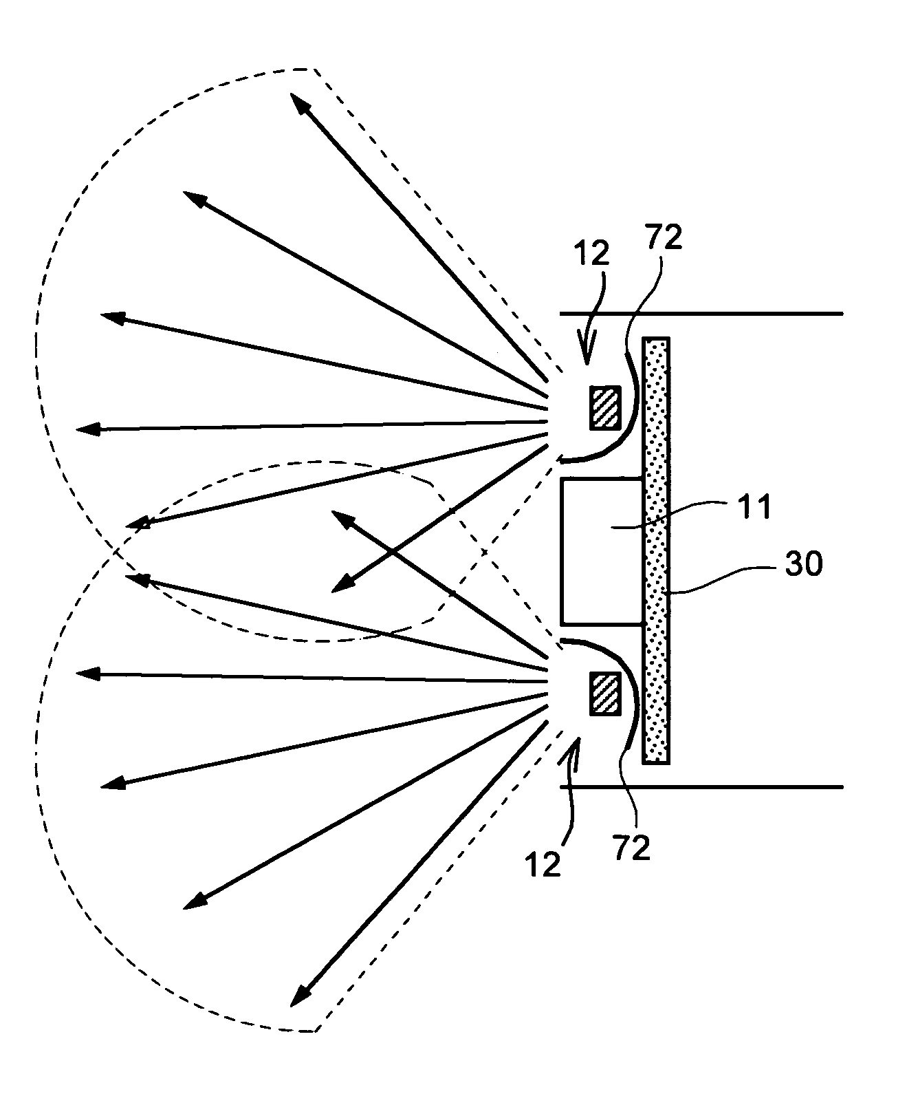
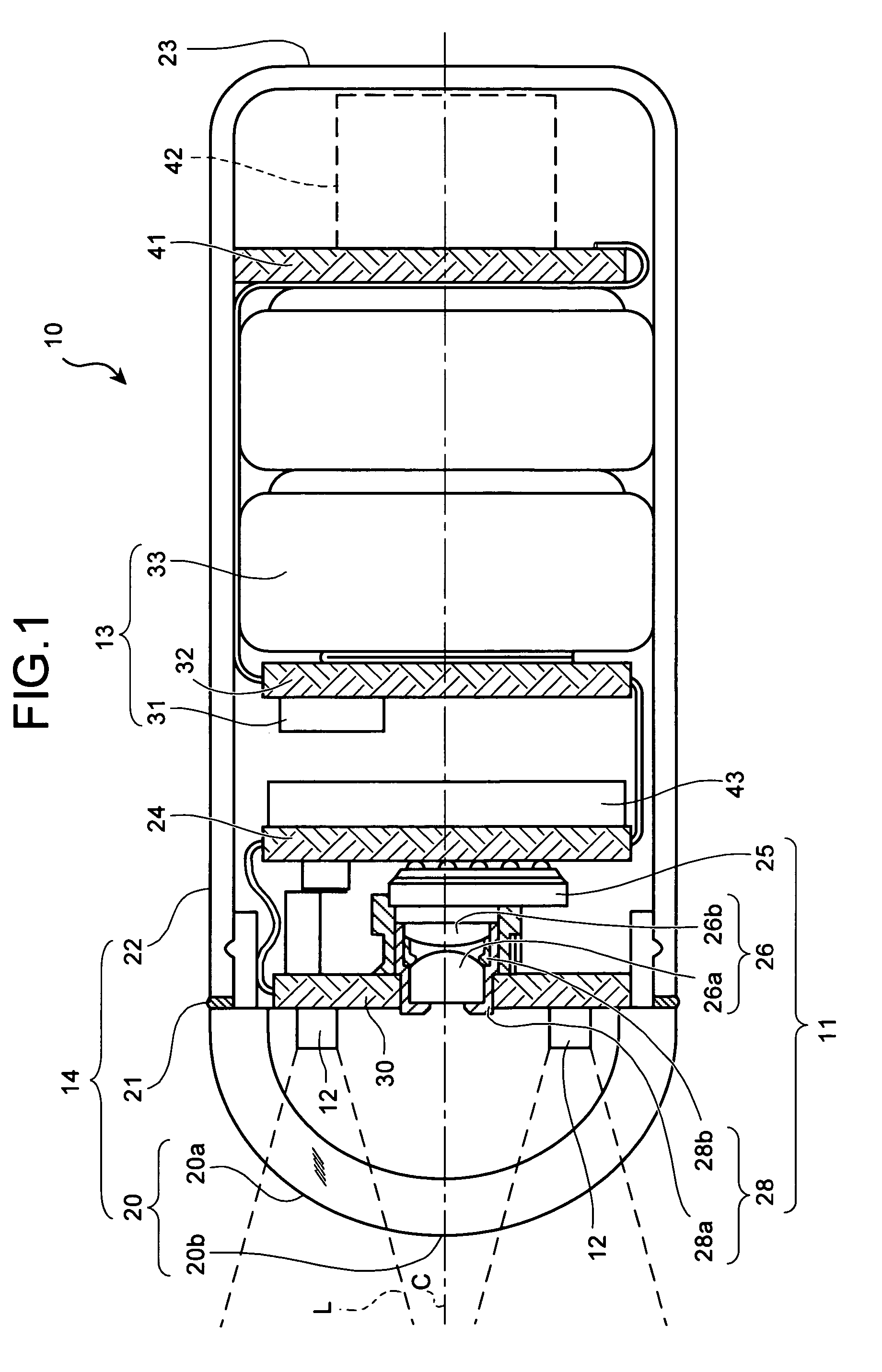
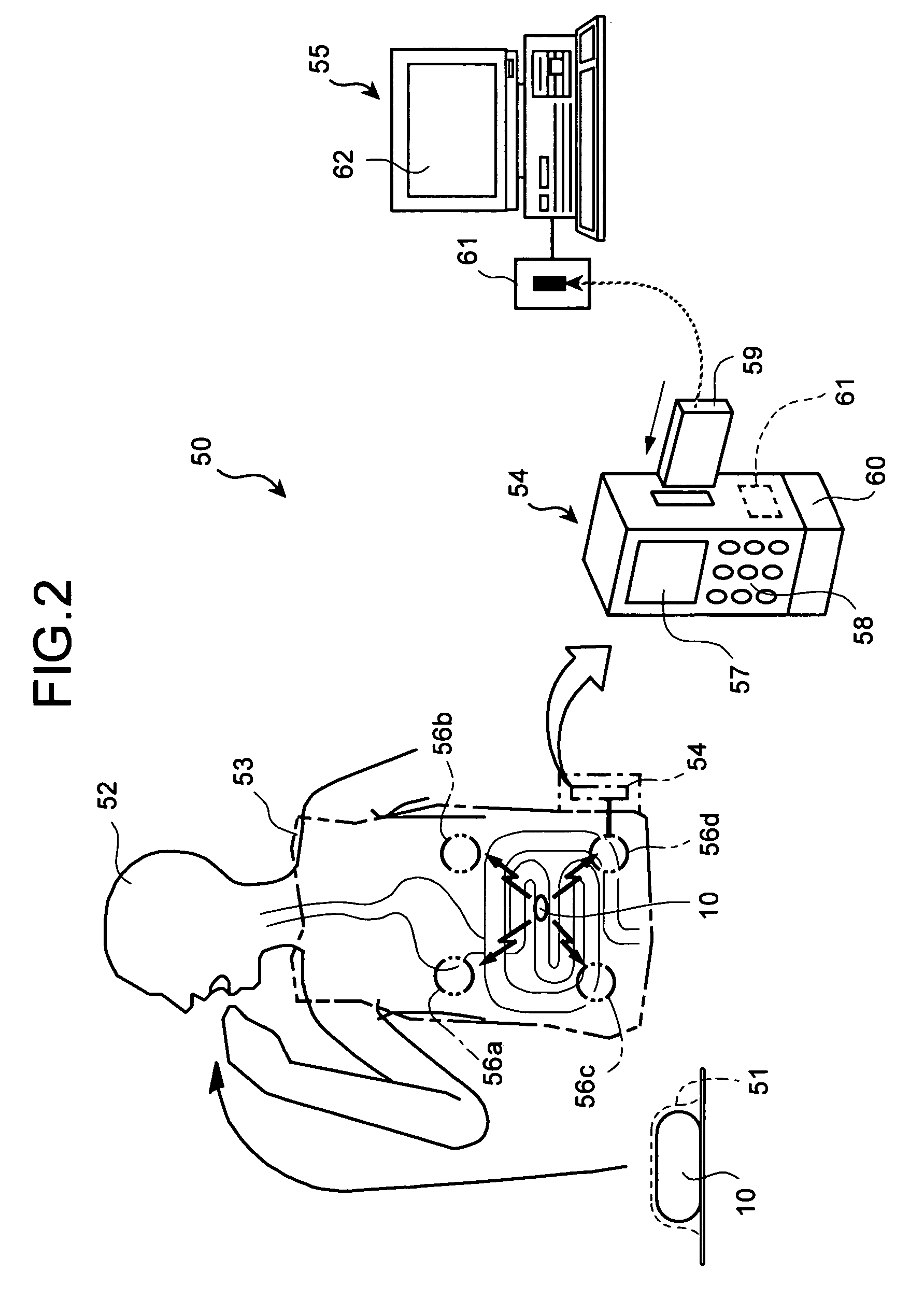
[0026]FIG. 1 is a schematic diagram of an internal structure of a capsule endoscope according to the present invention; FIG. 2 is a schematic diagram of a capsule endoscope system; FIG. 3 is a front view of a capsule endoscope according to one embodiment; FIG. 4 is a schematic diagram for explaining emission of a light from an illuminating unit of the capsule endoscope shown in FIG. 3; FIG. 5 is a schematic diagram to explain intensity of the light emitted from the illuminating unit of the capsule endoscope shown in FIG. 3.

[0027]FIG. 1 is a schematic diagram of an internal structure of a capsule endoscope according to the present invention and FIG. 2 is a schematic diagram of a capsule endoscope system

[0028]An overall internal structure of the capsule endoscope 10 is described by referring to FI...


PUM


Abstract

In a capsule endoscope illuminating units are disposed around an image capturing unit in such a manner that an optical axis of the illuminating units do not intersect with an optical axis of the observation unit, and illumination areas of the illuminating units overlap at substantially a central portion of an image capturing area of the image capturing unit.

Description

BACKGROUND OF THE INVENTION[0001]1) Field of the Invention[0002]The present invention relates to swallowable and capsule-shaped endoscopes and a capsule endoscope system.[0003]2) Description of the Related Art[0004]Swallowable and capsule-shaped endoscopes are known in the art. A patient swallows such a capsule endoscope and as the capsule endoscope passes through an abdominal cavity, it captures images of a stomach, intestines etc. An example of such a capsule endoscope is described below with reference to FIG. 9.[0005]As shown in FIG. 9, the conventional capsule endoscope includes a watertight capsule casing 8 having a front cover 5. The capsule casing 8 houses an image capturing unit 1 that captures images of an inside the abdominal cavity, an illuminating unit 2 that outputs a light to illuminate the inside of the abdominal cavity, a power-supply unit 3 that supplies power to the image capturing unit 1 and the illuminating unit 2.[0006]The illuminating unit 2 and the image captu...

Claims


Application Information

Patent Timeline
IPC IPC(8): A61B1/06
CPCA61B1/041A61B1/0607A61B1/0684A61B1/0625
Inventor KIMOTO, SEIICHIROFUJIMORI, NORIYUKISUZUSHIMA, HIROSHISHIGEMORI, TOSHIAKINAKAMURA, TSUTOMUNAGASE, AYAKOMINAI, TETSUOSHIMIZU, HATSUOHONDA, TAKEMITSUSASAGAWA, KATSUYOSHISUZUKI, KATSUYAHASHIMOTO, MASAYUKIORIHARA, TATSUYANAKATSUCHI, KAZUTAKA
Owner OLYMPUS CORP
Why Eureka
Try Eureka