Dynamic flange seal and sealing system

a sealing system and dynamic technology, applied in the field of sealing systems and dynamic flange sealing systems, can solve the problems of flange design and use, varies relative size and complexity of flanges, and achieve the effect of improving flange-to-flange connections

Inactive Publication Date: 2008-01-08
CURTISS WRIGHT FLOW CONTROL CORP
View PDF26 Cites 37 Cited by
  • Summary
  • Abstract
  • Description
  • Claims
  • Application Information

AI Technical Summary

Benefits of technology

[0010]In light of the deficiencies in the prior art, the present invention seeks to improve flange to flange connections by providing a seal that accounts for cyclical variations of temperature and pressure between flanged components.
[0011]Therefore, it is an object of some embodiments of the present invention to provide a flexible or dynamic flange seal and sealing system that provides an improved seal between flanged components.
[0012]It is another object of some embodiments of the present invention to provide a dynamic flange seal and sealing system that can withstand high temperature, high pressure environments by adjusting to structural and / or environmental changes often experienced in an extreme environment.
[0016]In one exemplary embodiment of the seal system, two iconel bellow seals are contained and supported within a recess formed in a first flange of a first component or member, wherein the iconel bellows seals are separated by a seal stainless steel annular spacer. The iconel bellows seal functions to provide a biased, dynamic seal by allowing for and providing adjustments within the seal as dictated by the existing conditions experienced between the flanges. Stated another way, the iconel bellows seal is capable of expanding to maintain a seal even when the flanged components separate slightly from each other, to maintain the integrity of the seal.
[0018]Preferably, the iconel bellows seal provides even further sealing by applying a silver seal to the milled recess in the flanges before and after inserting the bellows seals and spacers. The silver seal or other sealant may be omitted at the location where the inner bellows seal contacts the flange joint near the interior of the drum. This allows a small amount of steam to flow under pressure behind the blows seal and to the drum to pressurize the passage to contamination from coke from the contacting the down seal and to assist in monitoring the states of the seal. Of course, if necessary or desired, the iconel bellows seal could be sealed entirely so as to allow no fluid transfer therethrough. Likewise, the iconel bellows seal could be secured within the flange using no seals. In a semi-sealed configuration, the fluid flow is preferably specifically controlled using various means, such as via a steam inlet and purge system and associated control and monitoring module.
[0020]The present invention dynamic flange seal and sealing system is particularly suited for operation or use with a delayed coking process, and specifically between the various components present within a delayed coking system, such as a coke drum, a header, a de-header valve, a transition spool, an inlet feed, or a bonnet. Each of these component structures are coupled to one another, respectively, via their flanged segments and require a proper seal therebetween to function properly. Providing the flange connections within a delayed coking process with the present invention dynamic flange seal and sealing system provides many advantages, including, but not limited to, improving the integrity of the flange seals, the ability to account for structural and environmental changes without breaching the seals, and improving the overall efficiency of the coking process.

Problems solved by technology

In virtually every conduit or pipe installation where moderate to high pressures and temperatures exist, a problem is encountered when it comes to flange design and usage.
Most problems either reside in the actual connection itself, the means used to connect the flanges together, or the seal existing and desired there between.
The relative size and complexity of these flanges varies with the size of the needed components.
However, elastic materials, while useful in many settings, are not suited for high pressure, high temperature environments for obvious reasons.
Indeed, elastic gaskets typically are utilized only in settings where the temperature is kept below 250 degrees F. In addition, elastic gaskets tend to wear out relatively quickly, especially when subject to extreme conditions.
Any degradation of the seal existing between connected flanged components usually means that the system will experience leaks and other failures.
For these reasons, elastic gaskets are less than desirable for use in many settings.
However, because metallic gaskets are less elastic, they cannot generally be reused.
Moreover, metallic gaskets are subject to leaks caused by various stresses (and stress relief) and creep.
However, a problem with the Batzer seal is that as the size of the seal increases the flange size must also increase.
As such, large seals require abnormally and oftentimes prohibitively large flanges.
Also the seal is typically positioned along an edge, which makes the seal more vulnerable to corrosion or damage.

Method used


Image

  • Dynamic flange seal and sealing system
  • Dynamic flange seal and sealing system
  • Dynamic flange seal and sealing system

Examples


Embodiment Construction

[0030]It will be readily understood that the components of the present invention, as generally described and illustrated in the figures herein, could be arranged and designed in a wide variety of different configurations. Thus, the following more detailed description of the embodiments of the system and method of the present invention, and represented in FIGS. 1 through 6, is not intended to limit the scope of the invention, as claimed, but is merely representative of the presently preferred embodiments of the invention.

[0031]The presently preferred embodiments of the invention will be best understood by reference to the drawings wherein like parts are designated by like numerals throughout.

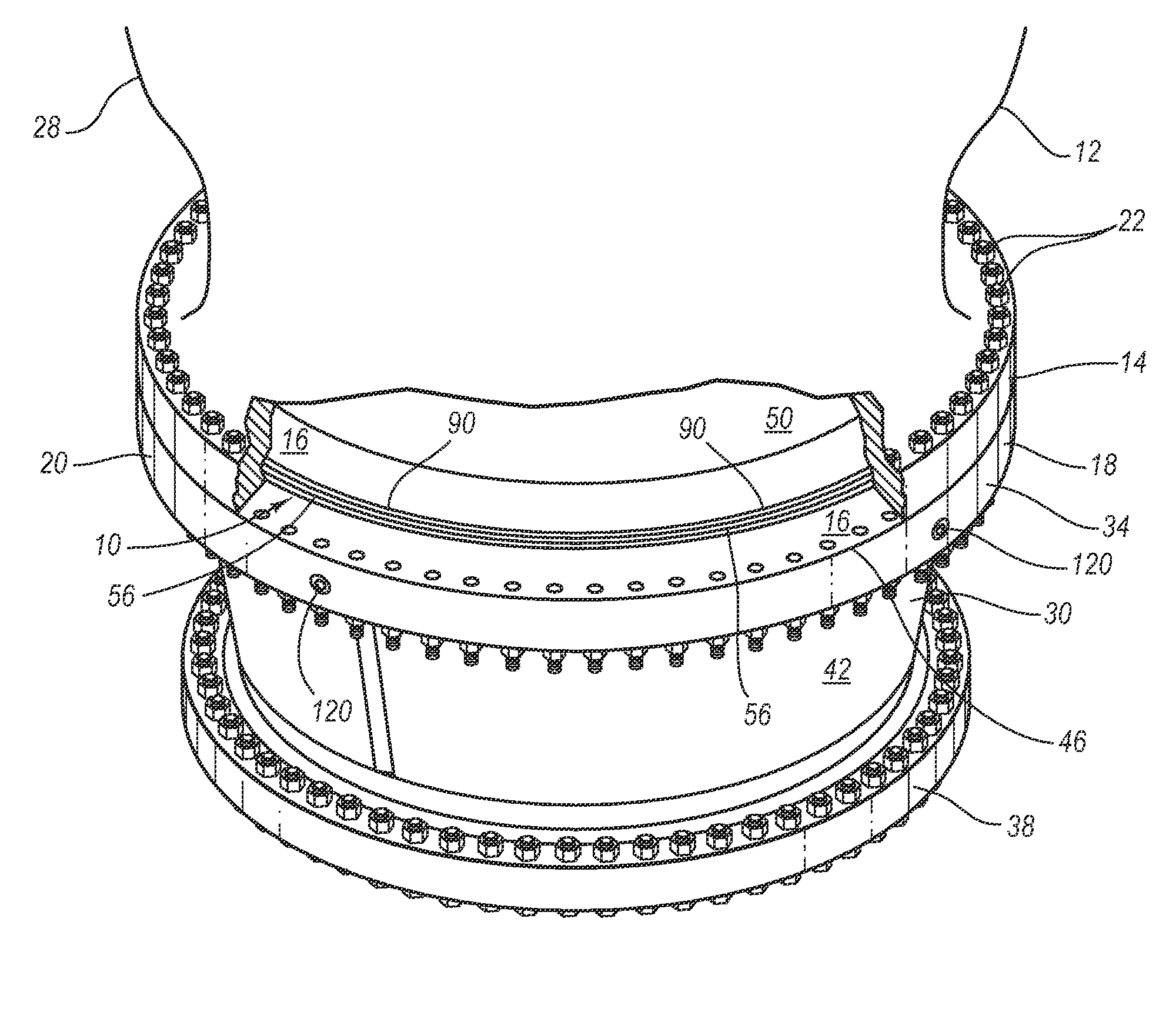
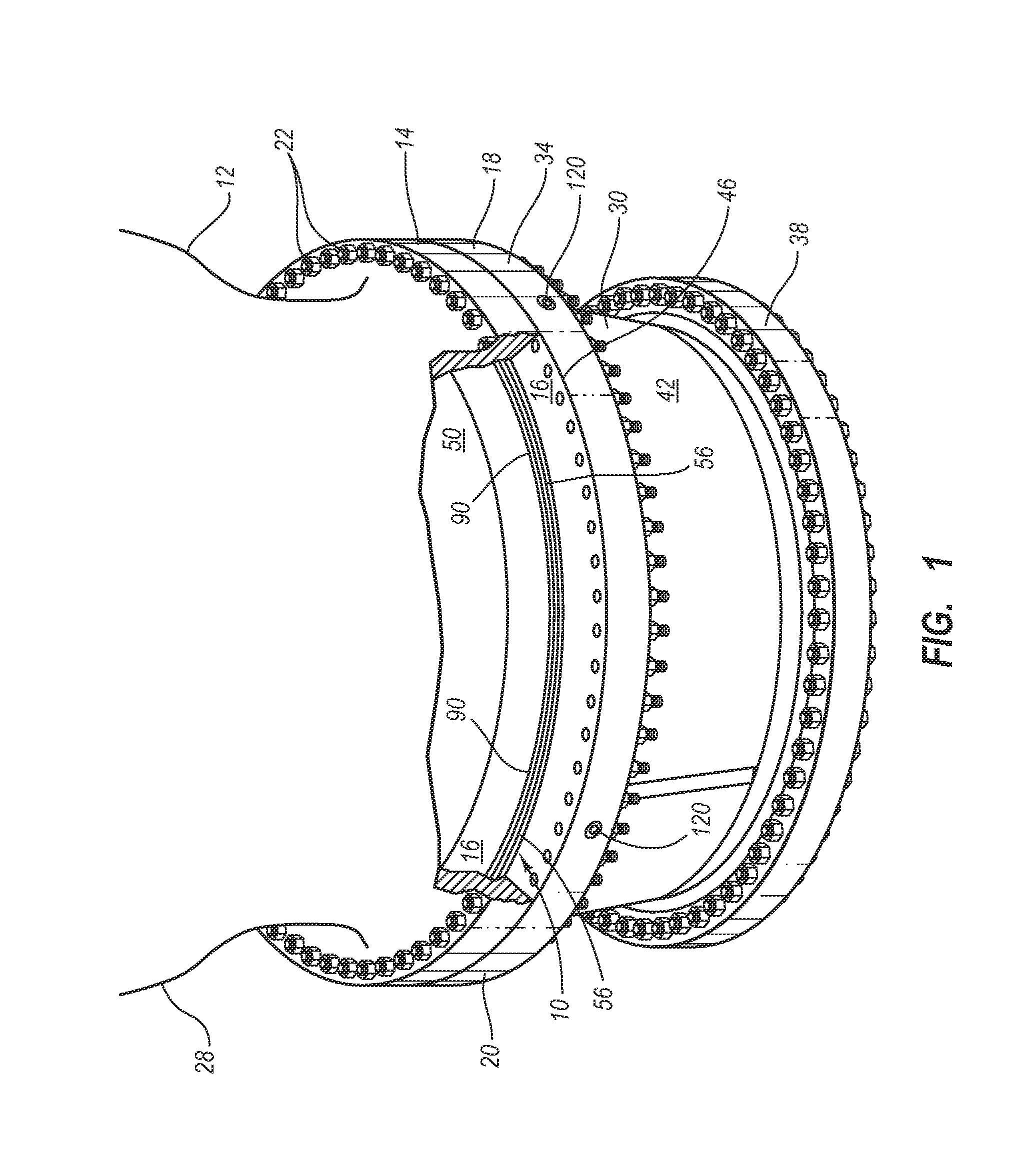
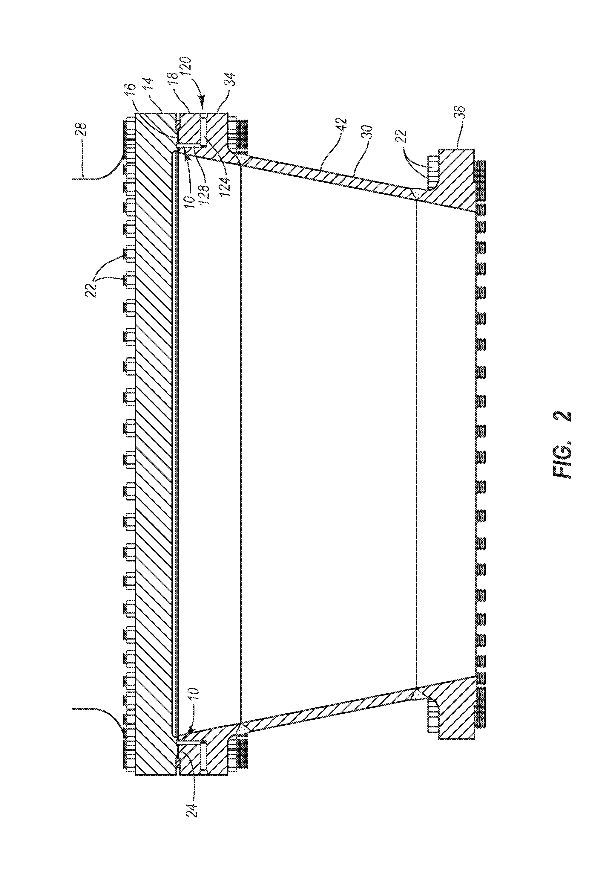
[0032]The present invention describes a method and system for providing a flange to flange seal using a dynamic flange seal and sealing system. With reference to FIG. 1, shown is a perspective view of one exemplary embodiment of a first flanged component 12 coupled to a second flanged component 2...


PUM

PropertyMeasurementUnit
temperatureaaaaaaaaaa
pressureaaaaaaaaaa
flexibleaaaaaaaaaa

Abstract

The present invention features a flange to flange dynamic seal and sealing system, particularly suited for use within high temperature, high pressure environments, such as a delayed coking process. The dynamic flange seal and sealing system comprises two primary elements or seals, each of which are capable of independently forming a flange seal between two flanged components or combining to create a flange seal. Specifically, these primary seals are an iconel bellows seal and a bi-material gasket, each of which surround a flange opening along a sealing surface. The flange seal created by the dynamic flange seal and sealing system is capable of being maintained in light of, or rather the sealing system adapts to, any structural or environmental changes within the connected flanges. As such, the flange seal may be a dynamic flange seal or a static flange seal or both.

Description

RELATED APPLICATIONS[0001]This application claims priority to U.S. patent application Ser. No. 09 / 946,917, entitled COKE DRUM BOTTOM DE-HEADING SYSTEM, filed Sep. 5, 2001, listing the same inventor as the application.BACKGROUND[0002]1. Field of the Invention[0003]The present invention relates to seals and dynamic sealing systems for sealing one or more connected flanges together, or generally a dynamic flange seal and sealing system for flanged components. The present invention more particularly relates to a dynamic flange seal and sealing system capable of forming a dynamic flange seal capable of adjusting with various structural or environmental changes in order to maintain the integrity of the seal existing between two or more connected flanges.[0004]2. Background of the Invention and Related Art[0005]In virtually every conduit or pipe installation where moderate to high pressures and temperatures exist, a problem is encountered when it comes to flange design and usage. Most prob...

Claims


Application Information

Patent Timeline
Patent Type & Authority Patents(United States)
IPC IPC(8): B01D3/14C10B25/00C08F2/00C10B25/10C10B25/16F16J15/08F16L23/20
CPCC10B25/10C10B25/16F16J15/0887F16L23/20
Inventor LAH, RUBEN F.
Owner CURTISS WRIGHT FLOW CONTROL CORP
Why Eureka
Try Eureka