Mounting arrangement for a refrigerator fan

a technology for refrigerator fans and mounting arrangements, which is applied in the direction of cooling devices, piston pumps, lighting and heating devices, etc., can solve the problems of difficult fixation and replacement of motors, disassembly of several other components, and obstruction of part of the air intake area of fans, etc., to achieve easy and rapid attachment

Inactive Publication Date: 2008-01-08
MULTIBRAS SA ELETRODOMESTICOS
View PDF10 Cites 31 Cited by
  • Summary
  • Abstract
  • Description
  • Claims
  • Application Information

AI Technical Summary

Benefits of technology

[0011]In function of the deficiencies pointed out above in relation to the prior art mounting arrangements, the present invention has the generic object to provide a mounting arrangement for a fan of the type considered herein, which is developed to assure an adequate absorption of the motor vibrations, utilizing a resistant construction which is easily and quickly assembled and disassembled and which presents good performance in the forced air circulation.
[0016]The construction proposed herein allows the fan to be easily and rapidly attached to the inner portion of the flexible support, whose outer portion is mounted to the internal divisional wall of the refrigerator, preferably by simply fitting a peripheral groove on the edge of the internal divisional wall that defines the contour of the opening of the refrigerated air outlet.

Problems solved by technology

However, this constructive arrangement presents some disadvantages, such as the obstruction of part of the air intake area of the fan and the difficult fixation and replacement of the motor, requiring the disassembly of several other components (propeller, ducts, mufflers, etc).
However, this prior art solution is not sufficiently resistant to transportation, allowing damages to occur to the fan.
The fact that the motor is directly affixed to the cabinet structure, having no cowlings for directing or conducting the airflow, results in efficiency loss of the forced air circulation system.
Besides the disadvantages mentioned above, the constructive solutions in which the motor is directly affixed to the cabinet by means of a rigid or flexible support make difficult or even infeasible to use fans provided from different suppliers, each fan requiring a respective adaptation for the motor support.

Method used


Image

  • Mounting arrangement for a refrigerator fan
  • Mounting arrangement for a refrigerator fan
  • Mounting arrangement for a refrigerator fan

Examples


Embodiment Construction

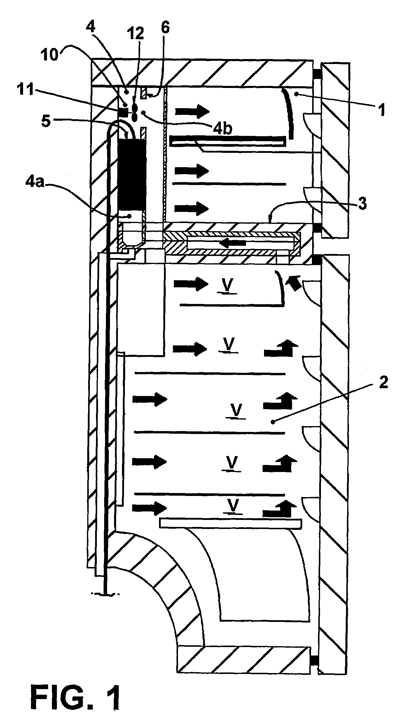
[0026]As illustrated in FIG. 1 and as already mentioned above, the invention is applied to a combined refrigerator with forced air circulation, comprising a freezing compartment 1 and a refrigerating compartment 2 which are superposed and separated by an intermediate wall 3. The refrigerator further comprises an air cooling compartment 4, generally located close to the rear region of the freezing compartment 1 and lodging an evaporator 5. The air cooling compartment 4 can be also applied in the rear upper region of a simple refrigerator with only one refrigerating or freezing compartment 2, 1, in order to provide refrigerated air to said compartment.

[0027]Independently of the type of refrigerator with forced air circulation to which it is applied, the air cooling compartment 4 presents a circulated air inlet 4a disposed upstream the evaporator 5, and a refrigerated air outlet 4b disposed downstream the evaporator 5 and which is provided through an internal divisional wall 6 of the r...


PUM


Abstract

A mounting arrangement for a refrigerator fan, comprising an electric motor (11) to whose shaft is affixed a propeller (12) with an axial flow passing through a refrigerated air outlet (4b) provided through an internal divisional wall (6) of the refrigerator; a support frame (20) having a marginal portion (21) and incorporating a central hub (22) in which is affixed the electric motor (11); a flexible support (30) in the form of an annular flange presenting an outer portion (31), which is peripherally and removably affixed to the contour of the refrigerated air outlet (4b), an inner portion (32) provided with a central opening (35) and with retaining means (36), which are removably locked to the marginal portion (21) of the support frame (20); and an annular membrane portion (33) interconnecting the outer portion (31) and the inner portion (32), in order to allow for small relative axial and radial displacements therebetween.

Description

[0001]This is a U.S. national phase application under 35 U.S.C. § 371 of International Patent Application No. PCT / BR2003 / 00059 filed Apr. 16, 2003 and claims the benefit of Brazilian Application No. PI 0201397-5 filed Apr. 19, 2002, The International Application was published in English on Oct. 30, 2003 as International Publication No. WO / 2003 / 089858 under PCT Article 21(2) the contents of both applications are incorporated herein in their entirety.FIELD OF THE INVENTION[0002]The present invention refers to a mounting arrangement for a fan used to provide the forced air circulation through the evaporator compartment in a refrigerator of the simple or combined types, in which each storing compartment defined inside a cabinet is submitted to an airflow that is forced to pass through the evaporator.BACKGROUND OF THE INVENTION[0003]In the refrigerators with forced air circulation, the evaporator is positioned inside an air cooling compartment generally provided in the rear upper region ...

Claims


Application Information

Patent Timeline
Patent Type & Authority Patents(United States)
IPC IPC(8): H02K5/24F04D29/60F04D29/66F25D17/06
CPCF04D29/601F04D29/668F25D17/065H02K5/24F25B2500/13F25D2201/30F25D2317/0653F25D2317/0681F25D2400/04
Inventor SCHMID, ALEXANDRE CURYCARGNIN, ADRIANOPEREIRA, ALEXSANDRO JOSERODRIGUES JUNIOR, ROGERIO
Owner MULTIBRAS SA ELETRODOMESTICOS
Why Eureka
Try Eureka