Screeding apparatus

a technology of squeezing apparatus and squeezing rod, which is applied in the direction of roads, roads, roads, etc., can solve the problems of inefficiency and relatively high cost of squeezing rod, and achieve the effect of low construction and maintenance cost and easy and efficient squeezing

Inactive Publication Date: 2008-01-15
BAVARO VITO A +1
View PDF9 Cites 2 Cited by
  • Summary
  • Abstract
  • Description
  • Claims
  • Application Information

AI Technical Summary

Benefits of technology

[0006]With the apparatus of the present invention, screeding of a concrete slab can readily and efficiently be accomplished without employing personnel utilizing shovels to do the back breaking work of pregrading poured concrete for the screed. In fact, the apparatus of this invention lends itself to operation by a single individual. Slabs are completed in an expeditious manner and the screeding machine has relatively low construction and maintenance costs as compared to other screeding apparatus employed when forming a screeding large slabs.

Problems solved by technology

This approach is relatively expensive and inefficient.

Method used


Image

  • Screeding apparatus
  • Screeding apparatus
  • Screeding apparatus

Examples


Embodiment Construction

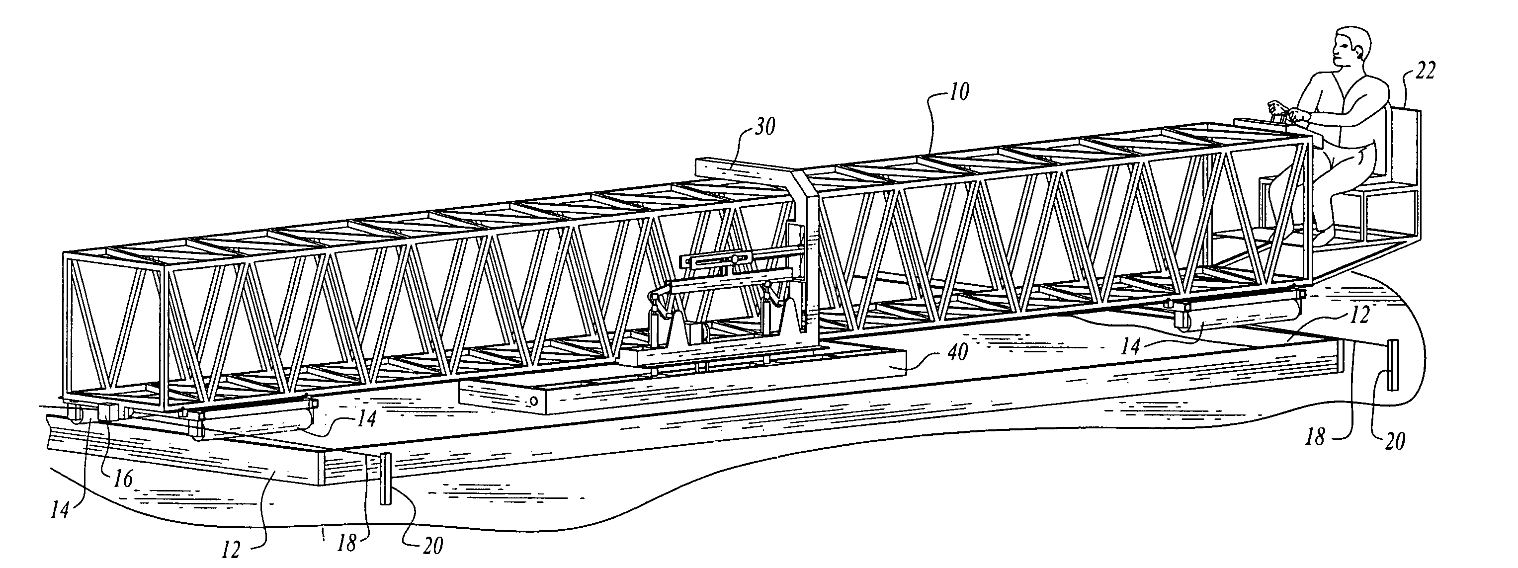
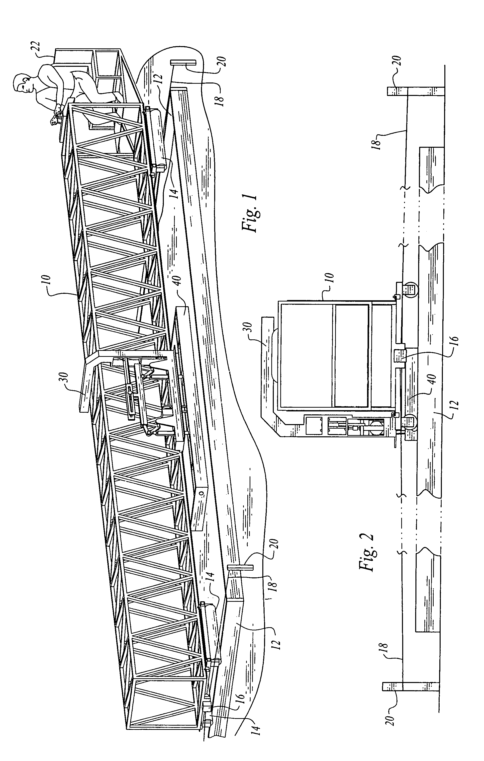
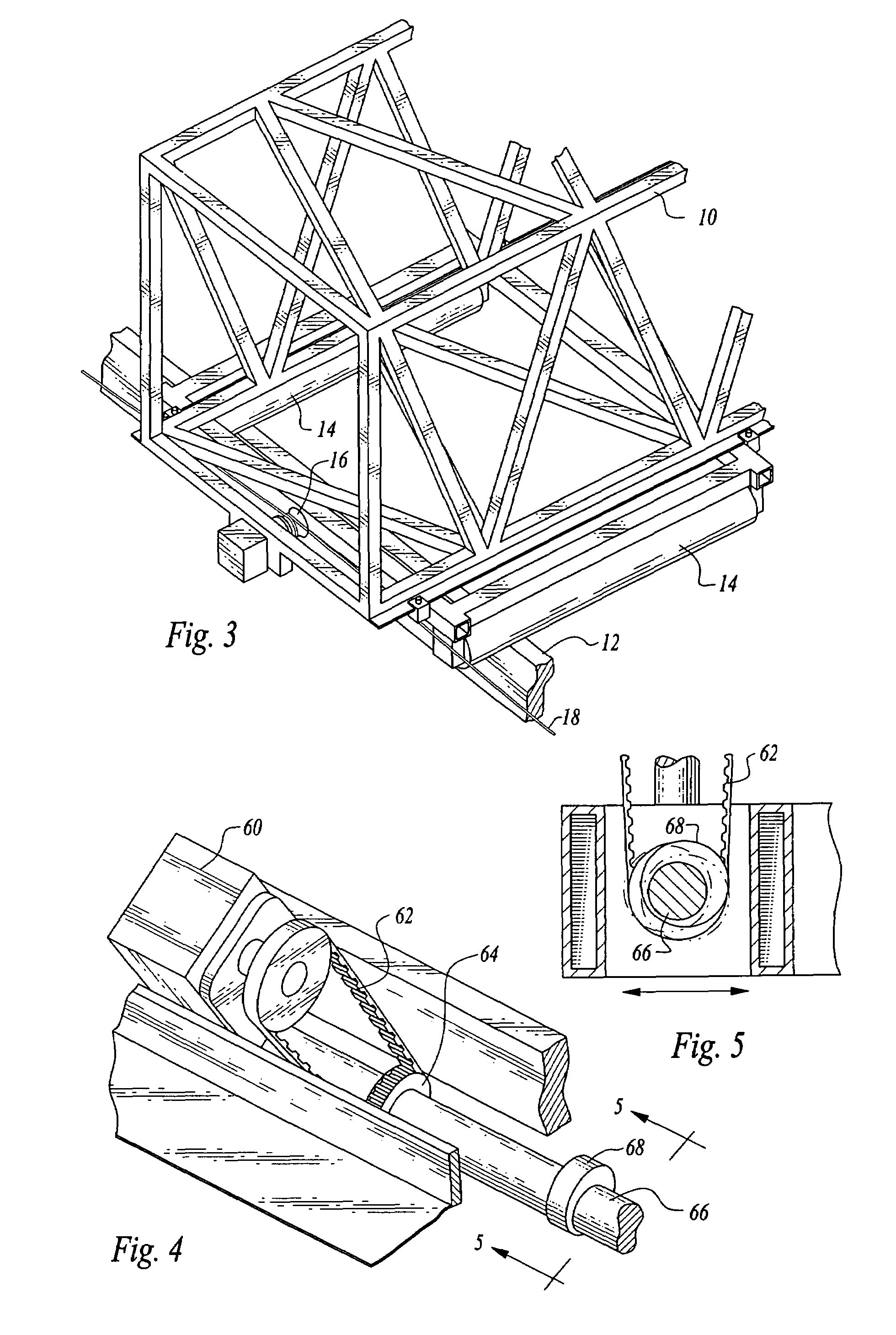
[0027]Referring now to FIGS. 1-8 of the drawings, a first embodiment of apparatus constructed in accordance with the teachings of the present invention includes a double-ended, elongated support in the form of an open framework or truss 10. The framework extends across and above a cavity defined by spaced side forms 12. Rollers 14 mounted at opposed ends of the elongated support are positioned on the spaced side forms.

[0028]The rollers 14 comprise components of support transport structure for transporting the framework 10 in a predetermined direction (corresponding to the direction of the side forms) along the spaced side forms. Hydraulic capstan winches 16 are located at the ends of the framework 10. Cables 18 extend along the lengths of the side forms, the ends thereof being held in place by stakes 20 or in some other manner. The cables 18 are wrapped about the rotating drums of the hydraulic capstan winches. Rotation of the winches will serve to move the framework either forward ...


PUM


Abstract

Screeding apparatus includes an elongated support and a strike board extending from a carriage on the elongated support, the support moved by drive structure along spaced side forms. The carriage and strike board are moved relative to the elongated support to engage, move and compact wet concrete within a cavity between said side forms during formation of a concrete slab.

Description

[0001]This application is a continuation-in-part of U.S. patent application Ser. No. 11 / 397,229, filed Apr. 3, 2006 now abandoned.TECHNICAL FIELD[0002]This invention relates to a screeding apparatus for engaging, moving and compacting wet concrete during formation of a concrete slab.BACKGROUND OF THE INVENTION[0003]Screeding of concrete to form slabs is a well known process. For small slabs, screeding is often accomplished by manual tools. Screeding machines exist for screeding larger slabs. The standard approach when using screeding machines is to have one or more workers employ shovels to perform the back breaking work of pregrading poured concrete for the screed. This approach is relatively expensive and inefficient.[0004]The following United States patents are believed to illustrate screeding equipment representative of the current state of the prior art in this field: U.S. Pat. No. 3,593,627, U.S. Pat. No. 4,132,492, U.S. Pat. No. 4,314,773, U.S. Pat. No. 4,340,351, U.S. Pat. N...

Claims


Application Information

Patent Timeline
Patent Type & Authority Patents(United States)
IPC IPC(8): E01C19/22
CPCE01C19/40
Inventor BAVARO, VITO A.BAVARO, LANCE WILLIAM
Owner BAVARO VITO A
Why Eureka
Try Eureka