Polymer processing systems including screws

a polymer processing system and screw technology, applied in the field of polymer foam material processing, can solve the problems of high l:d ratio of screws, inability to meet the aforementioned steps, and inability to meet the requirements of screw size, etc., and achieve the effect of increasing the cost of producing new or retrofitting systems that include screws with high l:d ratios

Inactive Publication Date: 2008-01-15
TREXEL
View PDF48 Cites 45 Cited by
  • Summary
  • Abstract
  • Description
  • Claims
  • Application Information

AI Technical Summary

Benefits of technology

[0010]In another embodiment, the invention provides a method of retrofitting a system previously used to process polymeric material by cyclically injecting polymeric material into a mold or cyclically ejecting polymeric material from a die. The system comprises an extruder including a first screw having a length and a diameter. The method comprising extending the downstream end of the barrel, e.g. by affixing an extension to the downstream end of the barrel, the extended portion including one or more blowing agent injection ports, and replacing the first screw with a replacement screw having a length greater (substantially greater, in some embodiments) than the length of the first screw. The replacement screw includes a restriction element positioned upstream of the location where a blowing agent port exists in the barrel, when the replacement screw is mounted in the barrel. The restriction element is designed to restrict the upstream flow of polymeric material therethrough during at least a portion of an injection or an ejection cycle. The replacement screw can also include, in one embodiment, a tip valve positioned at its downstream end. The tip valve permits downstream flow of polymeric material therethrough in an open configuration and restricts upstream flow of polymeric material therethrough in a closed configuration.

Problems solved by technology

Conventional injection molding or blow molding systems generally are not capable of satisfying all of the aforementioned steps needed to produce microcellular materials.
However, screws having high L:D ratios may be incompatible with existing conventional equipment used in injection and blow molding systems.
Furthermore, it may be more expensive to produce new or retrofitted systems that include screws having high L:D ratios.

Method used


Image

  • Polymer processing systems including screws
  • Polymer processing systems including screws
  • Polymer processing systems including screws

Examples


Embodiment Construction

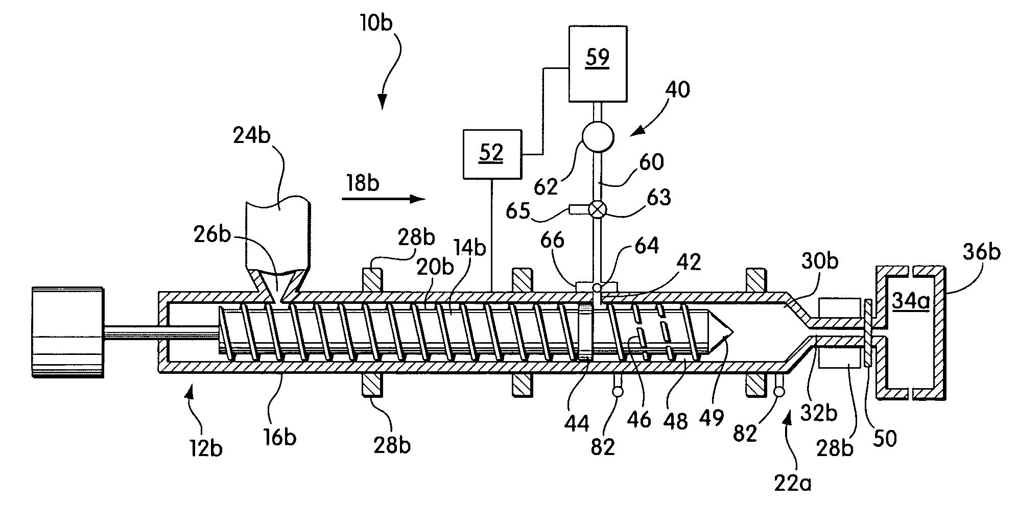
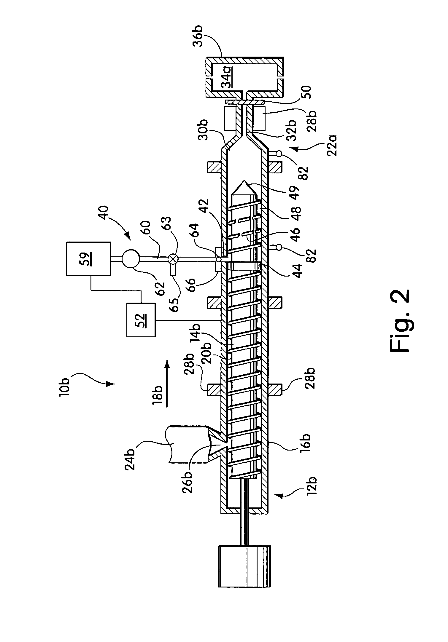
[0021]Injection molding and blow molding systems that include screws having low L:D ratios are provided. The systems are capable of producing microcellular polymeric materials. In some cases, the systems may be formed by retrofitting conventional polymer processing systems. Retrofitting may involve changing (e.g., machining or replacing) existing components of the conventional system, as well as, adding new components to the system. For example, retrofitting generally involves replacing the conventional polymer processing screw with a new screw designed to satisfy conditions needed for processing microcellular materials, as described further below. In other cases, the systems may be newly manufactured. The retrofitted or newly manufactured systems of the invention may be considerably less expensive than newly manufactured microcellular processing systems having higher L:D ratios.

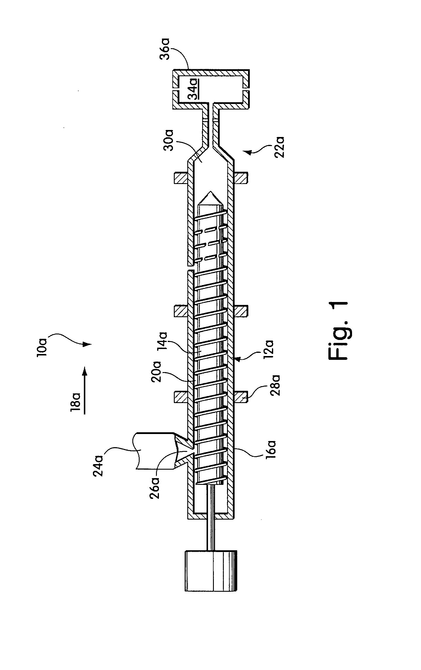
[0022]FIG. 1 schematically illustrates a conventional injection molding system 10a prior to being retrofi...


PUM

PropertyMeasurementUnit
average cell sizeaaaaaaaaaa
mass flow rateaaaaaaaaaa

Abstract

Injection molding and blow molding systems that include screws having low L:D ratios are provided. The systems are capable of producing microcellular polymeric materials. In some cases, the systems may be formed by retrofitting conventional polymer processing systems. Retrofitting may involve changing (e.g., machining or replacing) existing components of the conventional system, as well as, adding new components to the system. For example, retrofitting generally involves replacing the conventional polymer processing screw with a new screw designed to satisfy conditions needed for processing microcellular materials. In other cases, the systems may be newly manufactured. The retrofitted or newly manufactured systems of the invention are considerably less expensive than newly manufactured microcellular processing systems having higher L:D ratios.

Description

FIELD OF THE INVENTION[0001]The present invention relates generally to processing polymeric foam materials and, more particularly, to polymeric processing systems that include screws having short L:D ratios, as well as methods of retrofitting and using polymeric processing systems.BACKGROUND OF INVENTION[0002]Polymeric foam materials include a plurality of voids, also called cells, distributed within a polymer matrix. Microcellular foams (or microcellular materials) are a type of polymeric foam characterized by having small cell sizes and high cell densities. Microcellular foams may have a number of property and processing advantages.[0003]Certain processing steps may be required (or preferred), when forming microcellular foams. The steps include introducing blowing agent into polymeric material within an extruder, sufficiently mixing the mixture of polymeric material and blowing agent to form a homogeneous mixture within the extruder, maintaining a high pressure within the homogene...

Claims


Application Information

Patent Timeline
Patent Type & Authority Patents(United States)
IPC IPC(8): B29C44/38B29C44/34B29C45/00B29C45/23B29C45/50B29C48/395B29K105/04
CPCB29C44/3446B29C47/6018B29C47/6025B29C47/6062B29C47/6087B29C2045/1722Y10T29/49716B29C48/53B29C48/535B29C48/575B29C48/625B29C48/51
Inventor XU, JINGYICARDONA, JUAN C.KISHBAUGH, LEVI A.
Owner TREXEL
Why Eureka
Try Eureka