Localization device display method and apparatus

a technology of localization device and display method, applied in the field of medical instruments, can solve the problems of difficult to determine the direction the pointer needs to move to reach the reference location, requiring trial and error on the part, and the bone surface is relatively large, so as to achieve efficient selection

Active Publication Date: 2008-01-15
AESCULAP AG
View PDF8 Cites 125 Cited by
  • Summary
  • Abstract
  • Description
  • Claims
  • Application Information

AI Technical Summary

Benefits of technology

[0008]The present invention provides for display methods and apparatus that overcome the aforementioned problem by displaying different views based on the proximity of an instrument tracked by a localization device to a reference location identified by the localization device. The localization device displays different views, e.g., of different magnifications, based on the distance between the reference location identified by the localization device and the tip of the pointer being tracked by the localization device. By displaying different views based on the proximity of the pointer tip to the reference

Problems solved by technology

The actual surface of the bone is relatively large in comparison to the display area and it is difficult to determine the direction the pointer needs to move to reach the reference loc

Method used


Image

  • Localization device display method and apparatus
  • Localization device display method and apparatus
  • Localization device display method and apparatus

Examples


Embodiment Construction

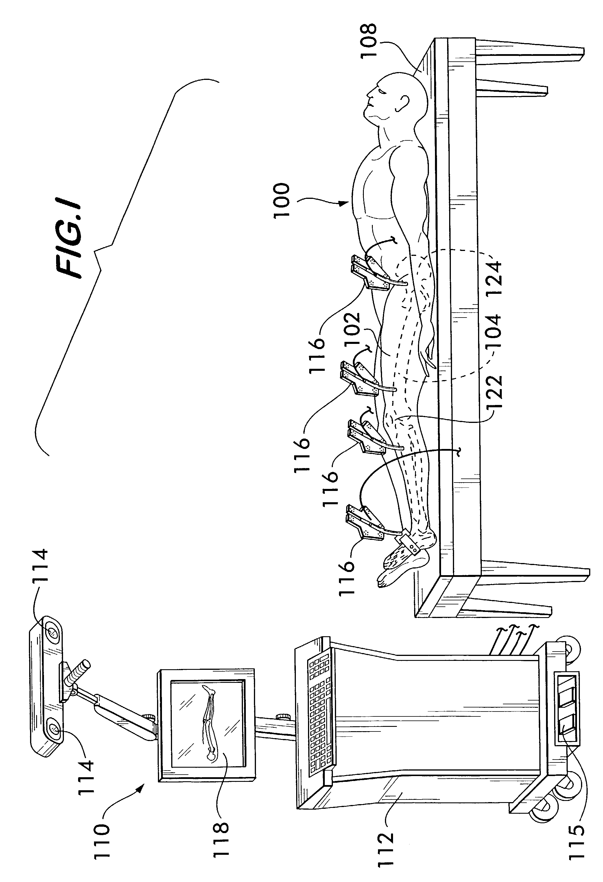
[0016]FIG. 1 depicts a localization device 110 in which the method of the present invention may be employed. For descriptive purposes, a preferred embodiment of the present invention will be described in connection with selecting the location for a tunnel within a femur 104 during an ACL repair procedure after a tibial tunnel for connecting a replacement ACL is drilled.

[0017]In FIG. 1, a patient 100, who is to undergo an ACL repair procedure on a leg 102 is illustrated schematically lying on an operating table 108. The localization device 110 includes a computer 112 loaded with software for surgical navigation, sensors 114, e.g., cameras, capable of detecting markers 116, and a monitor 118 for displaying surgical navigation information to a surgeon to help the surgeon select a location for drilling the femoral tunnel. The sensors 114 are positioned above and laterally from the patient 100 so that the patient's leg 102 is in the field of view of the sensors 114. In general, the marke...


PUM


Abstract

A localization device display method and apparatus for displaying different views, e.g., of different magnification, based on the proximity of the tip of a pointer tracked by the localization device to a reference location identified by the localization device. The display method and apparatus may be incorporated into a surgical navigation system for use in identifying a location for drilling a femoral tunnel in an ACL repair procedure.

Description

FIELD OF THE INVENTION[0001]The present invention relates to medical instruments and, more particularly, to a method and apparatus for displaying localization device information.BACKGROUND OF THE INVENTION[0002]Localization devices have been developed to assist surgeons in performing surgical procedures, e.g., anterior cruciate ligament (ACL) repair procedures. When utilized in an ACL procedure, markers are attached to bones that are observable by a stereoscopic camera system connected to a data processing system that records the positions of the markers in space to establish a coordinate reference system relative to each bone. Additional markers are used to palpate (touch) specific landmarks on the bones in order to ascertain the position of the landmarks in the coordinate reference systems of the bones. A monitor is used to display a representation of the bones that is based on the coordinate reference system and the landmarks for use in guiding a surgeon during the procedure. A d...

Claims


Application Information

Patent Timeline
IPC IPC(8): A61B5/05A61B17/17A61B19/00
CPCA61B17/1714A61B19/5244A61B19/5225A61B19/56A61B2019/505A61B2019/507A61B2019/5255A61B2019/5268A61B2019/5272A61B17/1764A61B2034/2055A61B2034/2068A61B2034/2072A61B34/20A61B34/25A61B2034/105A61B2034/107A61B90/37
Inventor LEITNER, FRANCOISDE CASSON, FRANCOIS BOUX
Owner AESCULAP AG
Why Eureka
Try Eureka