Controlled flame gas burner

a gas burner and controlled flame technology, applied in the field of gas burners, can solve the problems of inconvenient operation of the burner, difficulty in maintaining the burner,

Inactive Publication Date: 2008-01-29
BSH HOME APPLIANCES CORP
View PDF40 Cites 23 Cited by
  • Summary
  • Abstract
  • Description
  • Claims
  • Application Information

AI Technical Summary

Benefits of technology

[0004]The present invention overcomes the above mentioned disadvantages by providing a multiple piece burner with multiple fingers that includes location controlling structural features that supplement the flow of gas for flame generation and distribution about the periphery of the burner. One novel feature employed is the use of recesses in the burner body, preferably in the burner cap lip that extend above peripheral gas ports, whereby flame continuity can exist around the entire periphery of the burner despite its convoluted or contoured shape for distribution of flame kernels throughout the cooking top area. An additional feature serving to improve control of the gas flow through the burner involves at least one indexer that properly aligns the plurality of the burner parts with respect to each other without masking any minor misalignments which can affect the ability of the burner pieces to precisely control the gas flow. As a result, the present invention improves the simplicity of using and cleaning cooktops and improves a user's ability to properly operate a reassembled burner body.
[0005]In a preferred embodiment, the burner body comprises a burner head having a plurality of ports or port forming openings along a peripheral wall of each of the plurality of fingers. The burner head is covered by a cap having a corresponding number of overlapping fingers extending laterally beyond the peripheral wall in the burner head. A plurality of flame guides connecting adjacent ports are formed in the extending portion of the cap, or in the peripheral wall, so that adjacent flame kernels may be connected by an ignitable path of gas flow. This structure assures continuity of the flame at all peripheral ports regardless of their location, alignment or distance from the burner's central source of gas supply to the ports.
[0007]As a result, the present invention controls gas flow channels between displaceable burner parts by providing an indexing and nesting of the displaceable parts and assuring proper alignment in the nesting positions. In addition, the interaction of adjacent structures coupling the burner ports allows continuous flame generation between the ports so that continuity of flame around the irregular distribution of peripheral flame ports around the burner body is not affected by the distance from the gas supply or shaping of the body parts between the burner port inlets.

Problems solved by technology

Nevertheless, while such an arrangement improves distribution of the flames within a cooking top area, such irregularly shaped burners often have difficulty, particularly when sealed to the cooking top and subjected to various flow rates of primary air, in maintaining appropriately sized flame kernels throughout the irregular pattern of kernels throughout the cooking top area.
Slight misalignments may not be readily visible when parts have been prevented by some obstruction from nesting in a position that properly shapes the gas flow channels.
Such misalignments could adversely affect proper operation of the burner and interfere with generation and distribution of flame kernels, the formation of the kernels and the control of ignition of the proper flame.

Method used


Image

  • Controlled flame gas burner
  • Controlled flame gas burner
  • Controlled flame gas burner

Examples


Embodiment Construction

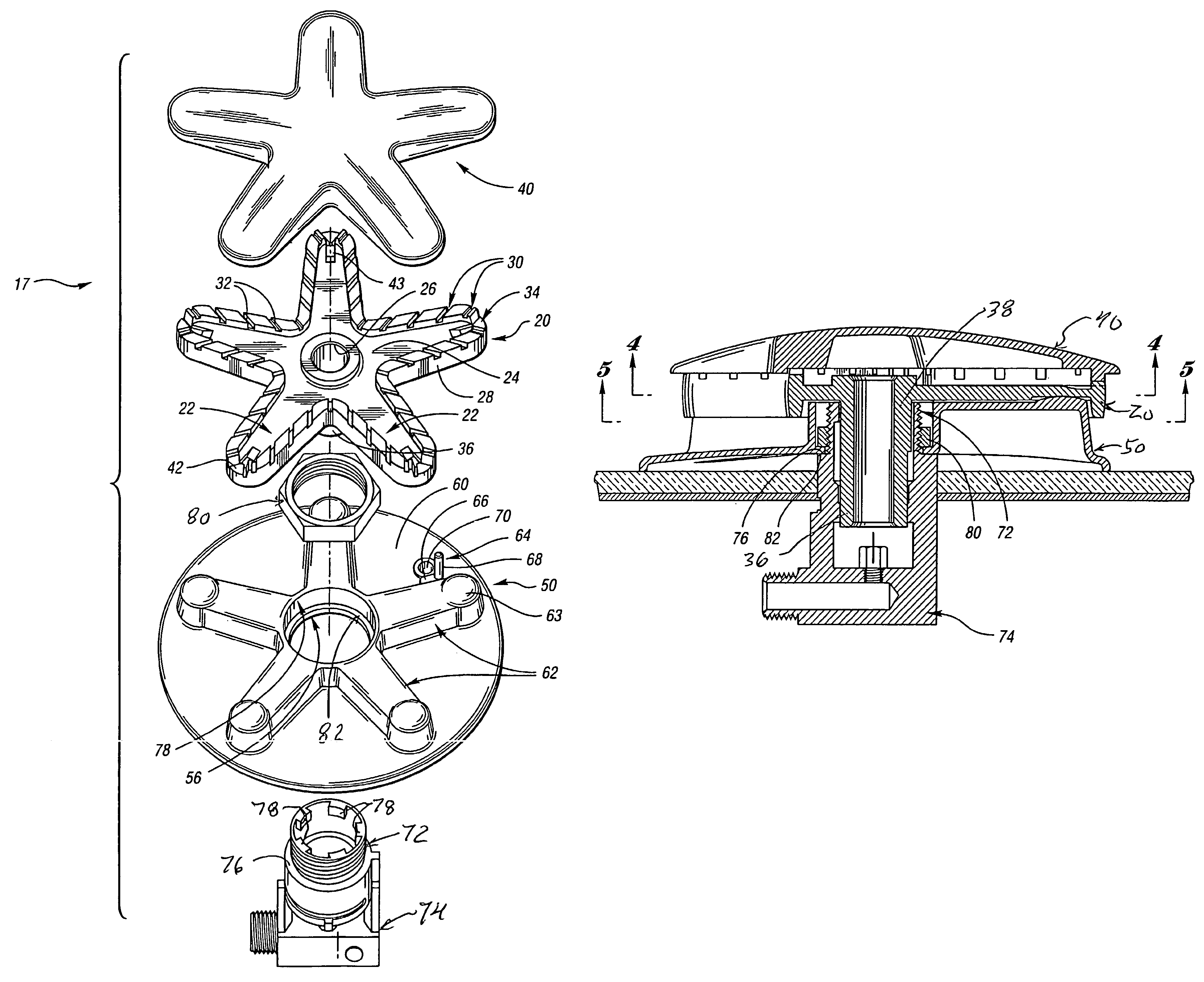
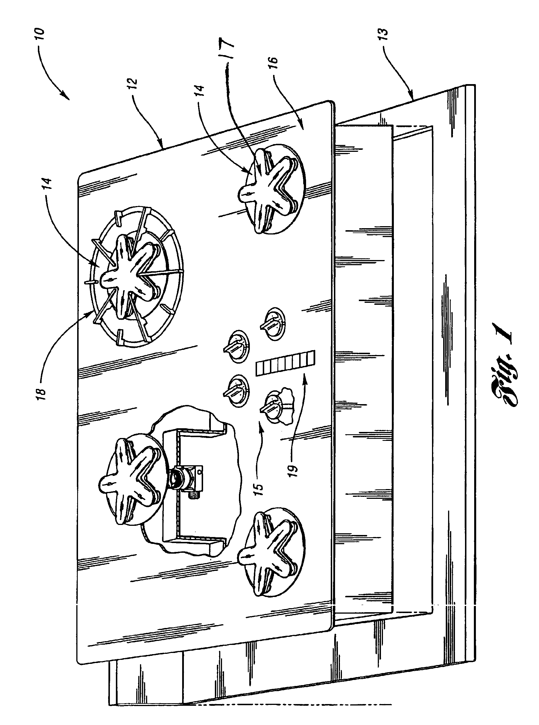
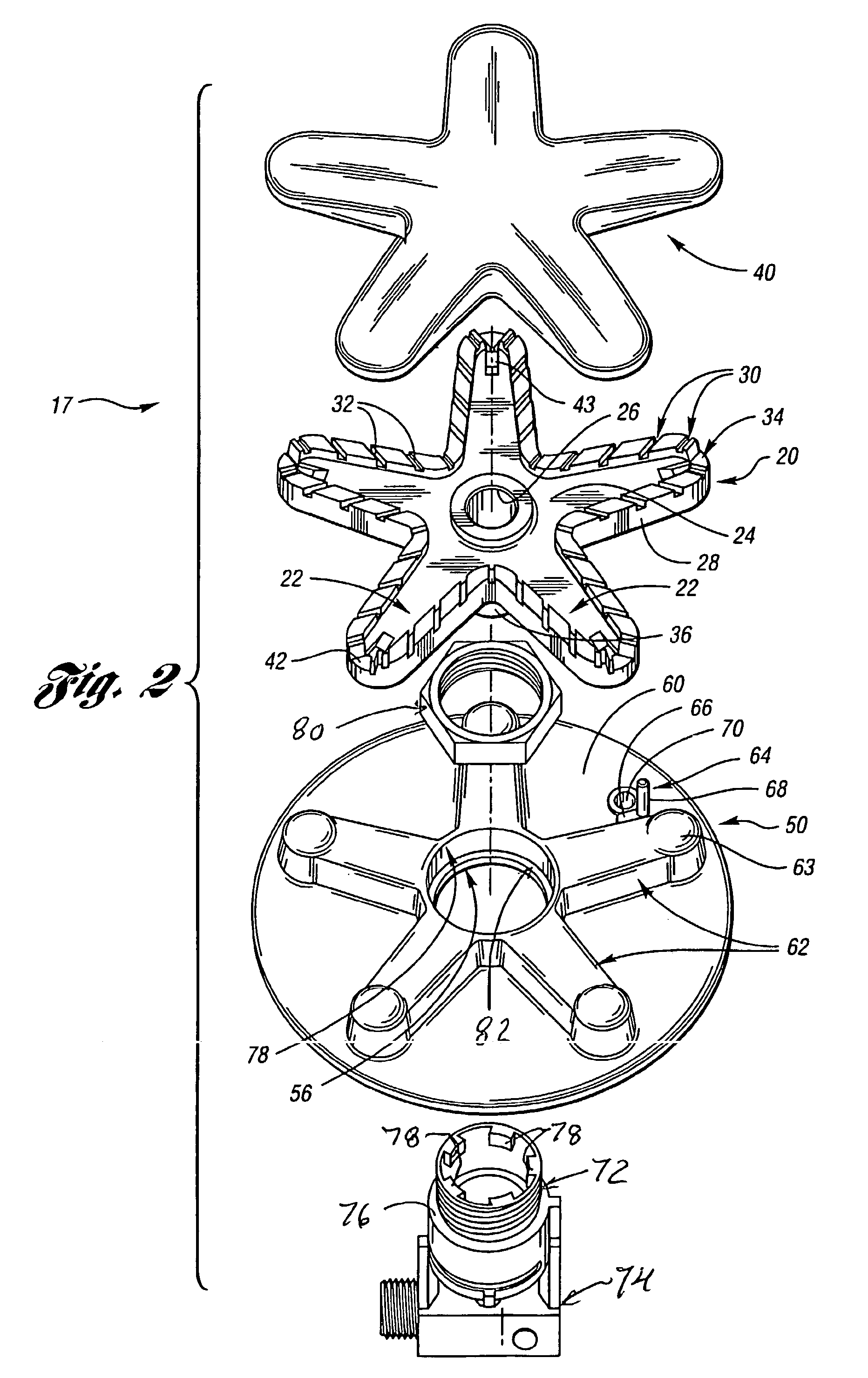
[0015]Referring first to FIG. 1, a cooktop appliance 10 is shown comprising a cooktop 12 fitting within a counter top 13. Nevertheless, it is to be understood that the appliance 10 may comprise a cooktop 12 adapted to be supported in a dedicated, fabricated housing or in a combined cooking appliance housing such as an oven, range, grill or other combination cooking appliance. In any event, the cooktop 12 includes a plurality of burners 14, although the location number and style of burners may be varied on the cooktop 12 without departing from the present invention. Nevertheless, at least one of the burners 14 includes a burner body 17 formed of a plurality of parts and the parts are interfitted so as to nest in a position that controls gas flow through and around the burner as will be described in greater detail below.

[0016]In addition, the cooktop 12 includes a plurality of controls 15 and indica 19 for operating the ignition and control of the gas supplied to each burner 14. Prefe...


PUM


Abstract

A multiple fingered burner includes controls for continuity of gas flow and ignition throughout all of the ports peripherally positioned around the contoured wall of the burner body. A plurality of burner parts are nested together with an indexer limiting insertion to at least one predetermined alignment in order to avoid improper fit or alignment between adjacent burner parts. In addition, the peripherally positioned ports are covered by a laterally extending lip of a cap, and at least one of the parts includes recesses adjacent the laterally extending lip to provide ignitable gas flow passages along the peripheral wall of the burner that maintain continuity of ignition at adjacent burner ports.

Description

THE FIELD OF THE INVENTION[0001]A gas burner for a cooking top includes a burner body with a plurality of fingers, a plurality of peripheral ports along each of the fingers and controls for gas flow along and through the fingers.BACKGROUND ART[0002]Although burners for controlling gas flow and flame generation in a cooking appliance have been known, a recent development that improves a flame spreading features within a controlled area so that the burner does not create a limited set of rings of heat application to a cooking utensil. For example, U.S. application Ser. No. 08 / 955,002, now U.S. Pat. No. 6,299,436, discloses a multiple fingered burner that expands the heating zone without exposing the peripheral ports in the fingers to exposure from spills occurring above the cooking top. Nevertheless, while such an arrangement improves distribution of the flames within a cooking top area, such irregularly shaped burners often have difficulty, particularly when sealed to the cooking top...

Claims


Application Information

Patent Timeline
Patent Type & Authority Patents(United States)
IPC IPC(8): F23D14/06F23D14/00F23D14/46F23D14/58F23D14/62F23Q3/00
CPCF23D14/06F23D14/58F24C3/085F23D2213/00F23D2900/14064
Inventor WELTON, JEFFREY A.JENNINGS, RALPH E.DAERENDINGER, HANS
Owner BSH HOME APPLIANCES CORP
Why Eureka
Try Eureka