Apparatus and method for removing enamel from a person's tooth

a technology of enamel removal and tooth, applied in the field of dental and orthodontics, can solve the problems of increasing the length and increasing the cost of the procedure, and affecting the effect of the patient's oral health, so as to reduce or eliminate the problems and disadvantages associated with the procedur

Active Publication Date: 2008-01-29
NAVARRO CARLOS F
View PDF16 Cites 12 Cited by
  • Summary
  • Abstract
  • Description
  • Claims
  • Application Information

AI Technical Summary

Benefits of technology

[0004]The apparatus and method of the present invention may reduce or eliminate certain problems and disadvantages associated with previous dental devices.
[0006]Particular embodiments of the present invention may provide one or more technical advantages. According to the present invention, an apparatus and method are provided for removing enamel from one or more of a person's teeth. The removal of enamel from one or both of two adjacent teeth may create space, or additional space, between the adjacent teeth. Thus, an IER procedure may be performed to prevent or treat the overcrowding of teeth associated with malocclusion and avoid the need for one or more tooth extractions. Additionally or alternatively, an IER procedure may be used to recontour or otherwise alter the size and shape of one or more of the person's teeth to provide a more aesthetically pleasing result.
[0007]In certain embodiments, the apparatus includes a one-piece integrally-formed frame, preferably metal, that provides strength and rigidity and is unlikely to break or otherwise fail during use. In certain embodiments, portions of the frame, including at least the handle portion, are enveloped or otherwise covered by a body, which may be made of plastic and may also be integrally-formed. In certain embodiments, the resulting handle may be manually gripped by an orthodontist or other clinical professional when using the apparatus to remove enamel from a person's tooth. In certain embodiments, the apparatus is lightweight and may be easily positioned and manipulated by the clinical professional. In certain embodiments, a driver mechanism may be used in cooperation with the frame to drive reciprocal motion of the abrasive surface of the blade portion of the frame against the enamel of a person's tooth. In certain embodiments, one or more apertures formed through the blade portion of the frame channel debris away from the interproximal contact area as an IER procedure is being performed. As a result, bits of removed enamel, saliva, blood and any liquids, chemicals, or pastes used in the IER procedure and present at the interproximal contact area may be channeled away from the tooth through the one or more apertures and the area kept cleaner and visibly unobstructed during the procedure, reducing or eliminating the need to interrupt the procedure to clean the interproximal contact area. In certain embodiments, the apparatus may be inexpensively mass manufactured such that it is economically practical to dispose of the apparatus after a single use, eliminating the need for cleaning and sterilization between uses. In certain embodiments, the handle may have a substantially circular cross-section with a substantially continuous circumference. The handle may also be substantially solid. As a result, the handle may be substantially non-deformable such that cross-sectional dimensions of the handle remain substantially constant when the handle is force-fitted into or otherwise coupled to a corresponding opening of a driver mechanism.

Problems solved by technology

Many people experience adverse conditions resulting from the overcrowding of teeth associated with malocclusion.
Because debris from the IER procedure accumulates around the interproximal contact area, the procedure must be interrupted and the interproximal contact area cleaned periodically during the procedure, adding to the length and cost of the procedure.
Additionally, tools used for IER are typically constructed from multiple pieces of metal coupled together using welds, rivets, or other means and can be expensive.
For economic reasons, these tools typically must be reused a number of times and therefore must be thoroughly cleaned and sterilized between IER procedures, further increasing costs associated with these procedures.
Such tools are also typically constructed using molded sheet metal, which results in poor structural integrity, negatively impacting their ability to couple to an associated driver mechanism and reducing their useful life.

Method used


Image

  • Apparatus and method for removing enamel from a person's tooth
  • Apparatus and method for removing enamel from a person's tooth
  • Apparatus and method for removing enamel from a person's tooth

Examples


Embodiment Construction

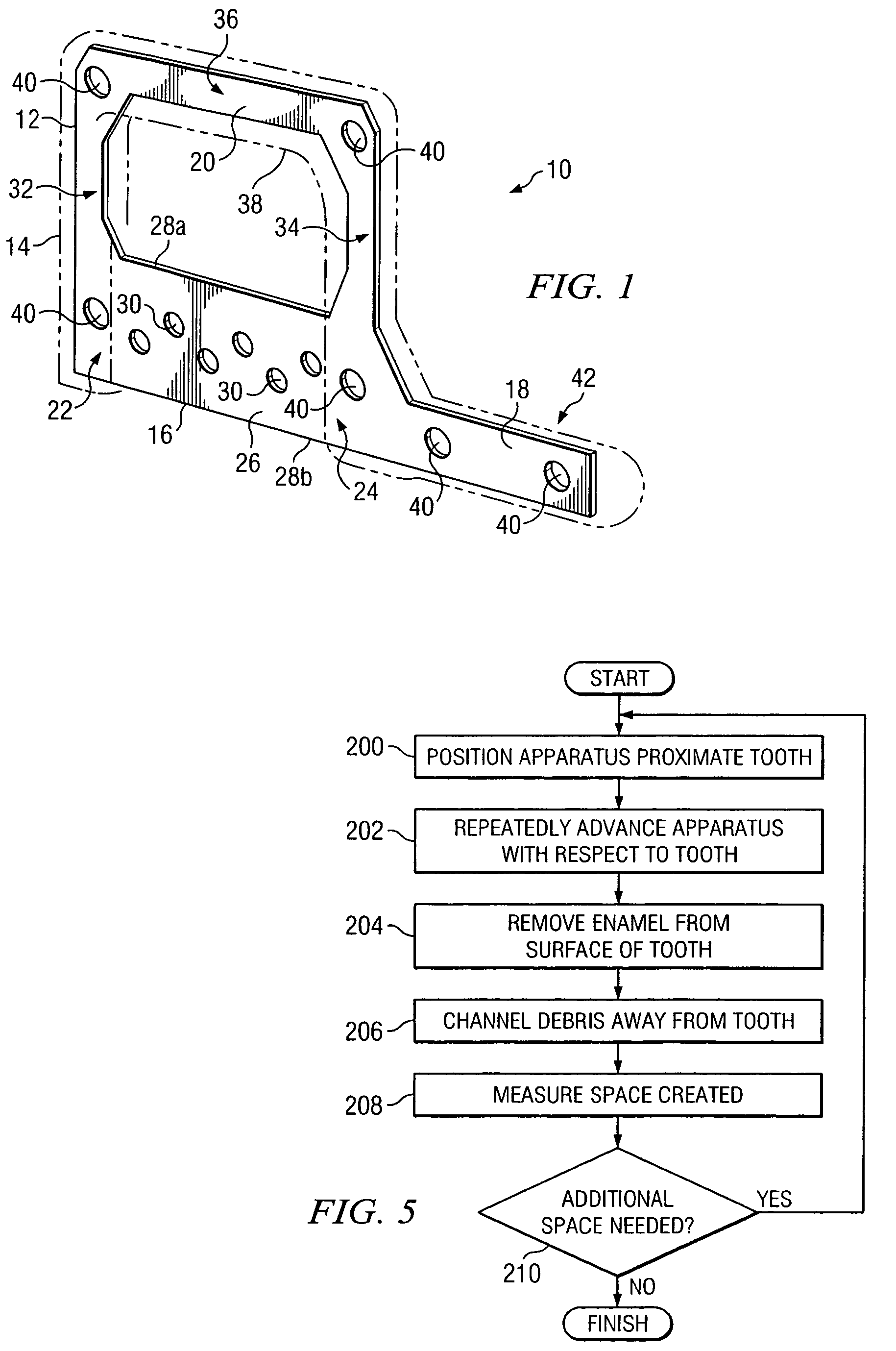
[0015]According to the present invention, an apparatus and method are provided for removing enamel from one or more of a person's teeth. The removal of enamel from one or both of two adjacent teeth may create space, or additional space, between the adjacent teeth. Thus, an IER procedure may be performed to prevent or treat the overcrowding of teeth associated with malocclusion and avoid the need for one or more tooth extractions. Additionally or alternatively, an IER procedure may be used to recontour or otherwise alter the size and shape of one or more of the person's teeth to provide a more aesthetically pleasing result.

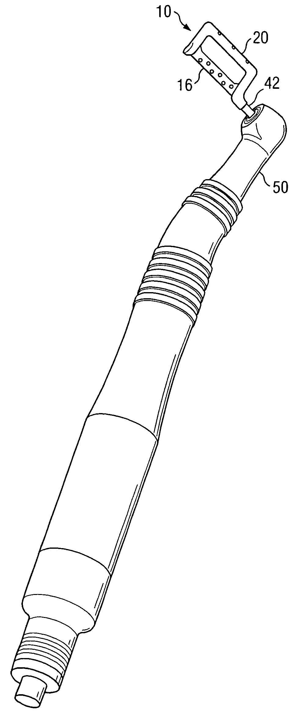
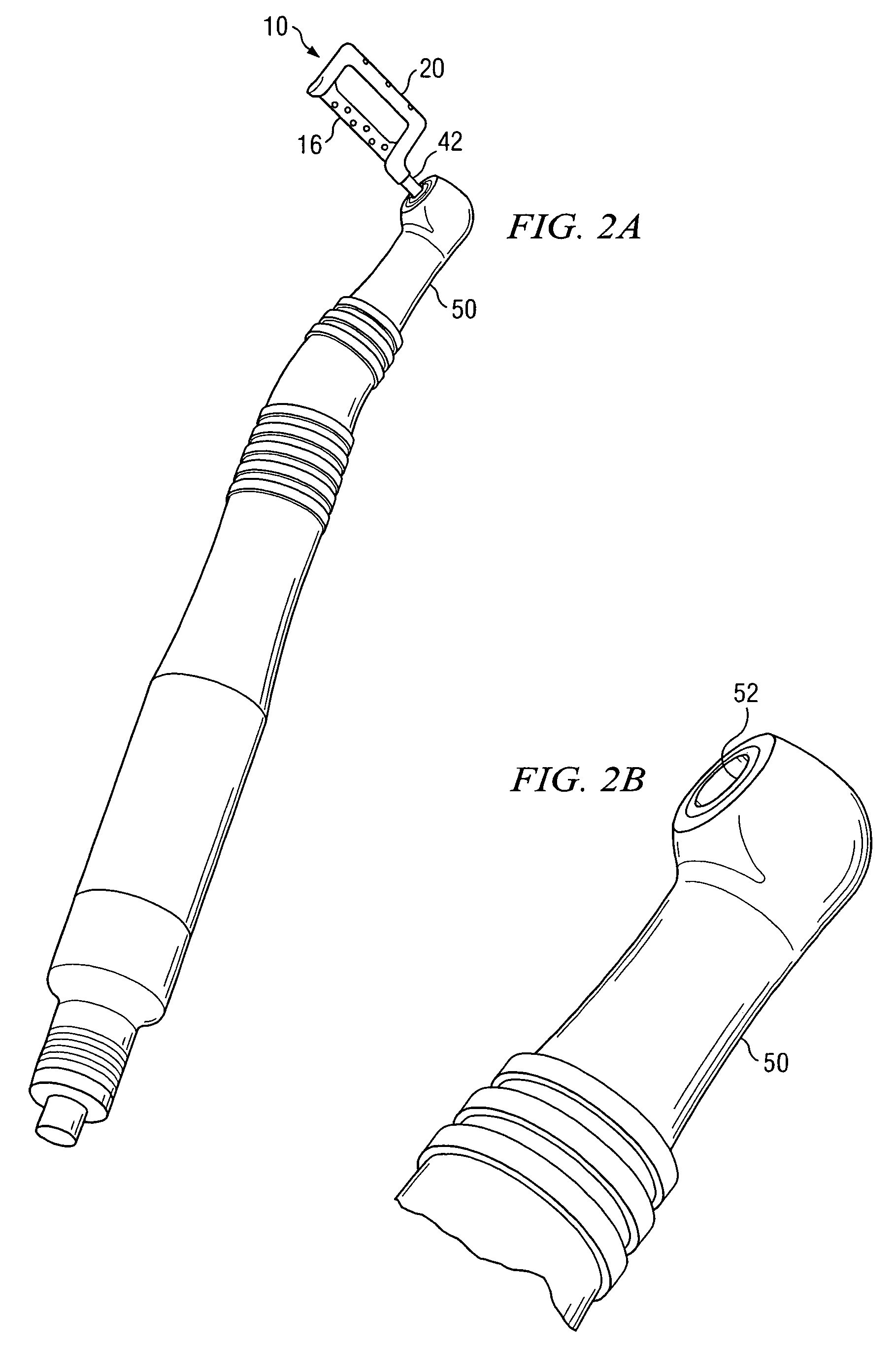
[0016]FIG. 1 illustrates an example apparatus 10 for removing enamel from a person's tooth. Apparatus 10 includes a frame 12 and a body 14. In certain embodiments, frame 12 is a one-piece frame integrally-formed from a single piece of material. Frame 12 may be made of steel or another metal. Body 14 is formed around frame 12 to envelop or otherwise cover appropriat...


PUM


Abstract

According to one embodiment, an apparatus for removing enamel from a person's tooth includes a blade portion and a handle portion. The blade portion includes an abrasive surface adapted to remove enamel from the tooth in response to reciprocating movement of the abrasive surface against the enamel of the tooth. The handle portion is coupled to the blade portion, has a substantially solid cross-section, and is adapted to be inserted into a corresponding opening in a driver mechanism that is adapted to drive reciprocating movement of the blade portion to provide the reciprocating movement of the abrasive surface.

Description

RELATED APPLICATIONS[0001]This application claims the benefit under 35 U.S.C. § 119(e) of U.S. Provisional Application Ser. No. 60 / 609,518 filed Sep. 13, 2004, U.S. Provisional Application Ser. No. 60 / 635,647 filed Dec. 13, 2004, and U.S. Provisional Application Ser. No. 60 / 683,623 filed May 23, 2005.TECHNICAL FIELD[0002]This invention relates generally to dentistry and orthodontics and in particular to an apparatus and method for removing enamel from a person's tooth.BACKGROUND[0003]Many people experience adverse conditions resulting from the overcrowding of teeth associated with malocclusion. To avoid the need for one or more tooth extractions, such conditions have been treated effectively by removing enamel from one or more teeth in the person's mouth to create space or additional space. Interproximal Enamel Reduction (IER) is the clinical act of removing part of the enamel from an interproximal contact area of a person's tooth. To perform IER, an orthodontist or other clinical p...

Claims


Application Information

Patent Timeline
Patent Type & Authority Patents(United States)
IPC IPC(8): A61C3/06
CPCA61C3/06A61C3/03A61C3/12
Inventor NAVARRO, CARLOS F.
Owner NAVARRO CARLOS F
Why Eureka
Try Eureka