Ultrasound diagnosis apparatus

a technology of ultrasonic and diagnostic equipment, applied in ultrasonic/sonic/infrasonic diagnostic equipment, instruments, applications, etc., can solve the problems of not being able to obtain beam profiles preferable to specific transmitting and receiving wave conditions, and none of these documents describes dynamically changing the shape of each sub-array. achieve excellent beam profiles

Inactive Publication Date: 2008-01-29
HITACHI LTD
View PDF36 Cites 28 Cited by
  • Summary
  • Abstract
  • Description
  • Claims
  • Application Information

AI Technical Summary

Benefits of technology

[0008]The present invention advantageously provides an ultrasound diagnosis apparatus capable of providing an excellent beam profile.
[0011]With the above structure, the switching section defines a plurality of sub arrays on the array transducer. Because the switching section has a function of changing the sub array shape pattern of the sub array, a conventional problem caused by fixedly defining the sub array shape pattern can be solved or improved. For example, due to the change of sub array shape pattern, a beam profile is changed to an excellent beam profile, whereby side lobes can be reduced.
[0013]Preferably, an identical sub array shape pattern is defined for a plurality of sub arrays. This structure facilitates close coupling of a plurality of sub arrays with respect to each other. It is of course possible to individually define the sub array shape pattern for each sub array.
[0017]For example, when n groups are set with respect to m transducer elements forming a certain sub array (1<n<m), a channel reduction ratio of n / m is achieved. By performing such a channel reduction process within the probe head, the advantage of reducing the number of signal lines inserted through the probe cable can be obtained. With such grouping, a plurality of receiving signals are summed and combined into a single receiving signal (a group receiving signal). Further, a single transmitting signal can be supplied in parallel to a plurality of transducer elements forming one group.
[0021]Preferably, a control section for switching the group shape pattern along with the sub array shape pattern in accordance with a beam forming condition is further provided. Preferably, the plurality of sub arrays are closely coupled with each other even when the sub array shape pattern is changed. When a plurality of sub arrays are closely coupled with each other, it is possible to operate a great number of available transducer elements, thereby increasing acoustic power.

Problems solved by technology

None of these documents, however, describes dynamically changing the shape of each sub array.
When the structure or form of the sub array is fixedly defined, a problem results in that a beam profile preferable to specific transmitting and receiving wave conditions cannot be obtained.

Method used


Image

  • Ultrasound diagnosis apparatus
  • Ultrasound diagnosis apparatus
  • Ultrasound diagnosis apparatus

Examples


Embodiment Construction

[0043]Preferred embodiments of the present invention will be described with reference to the drawings.

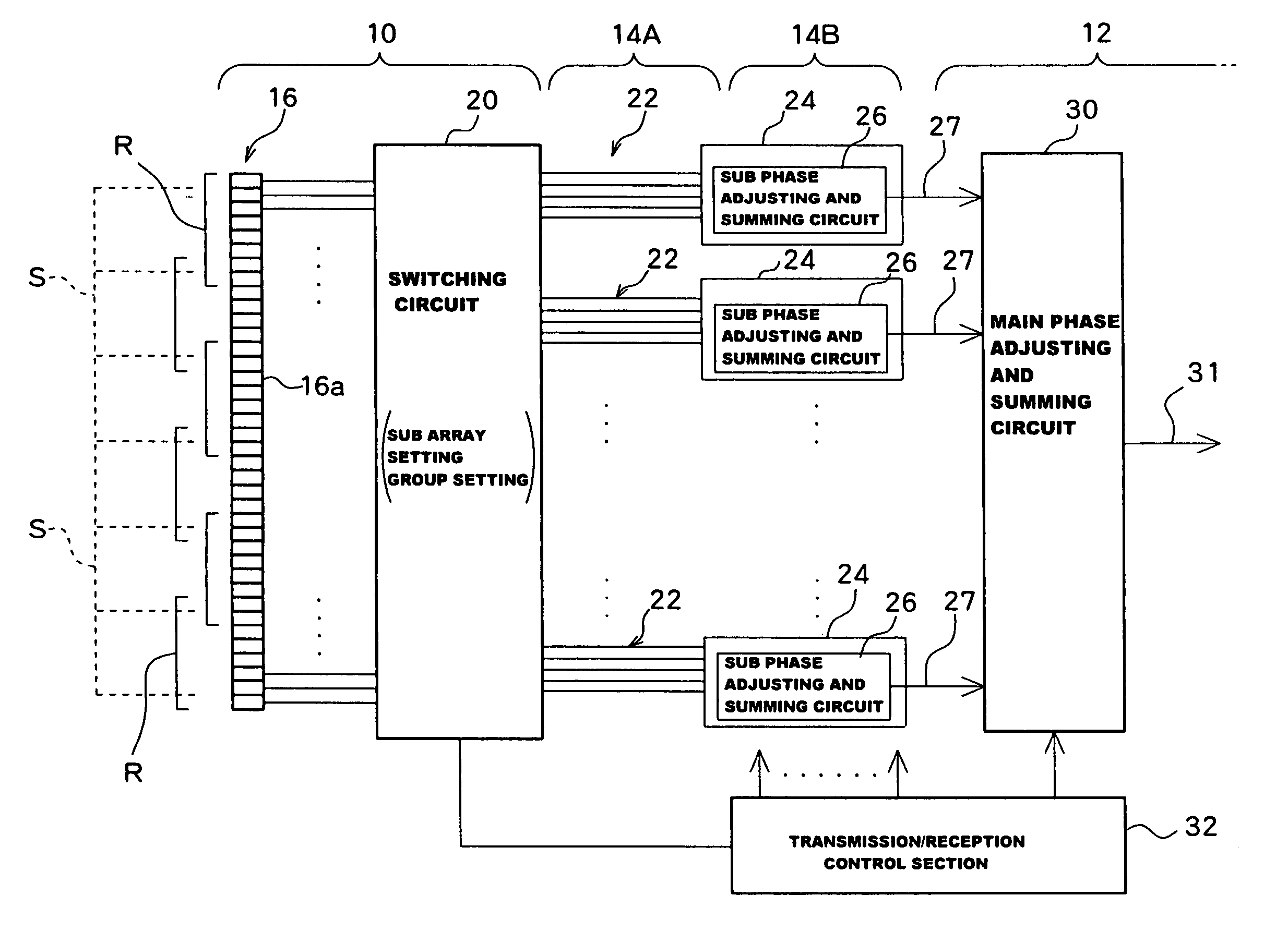
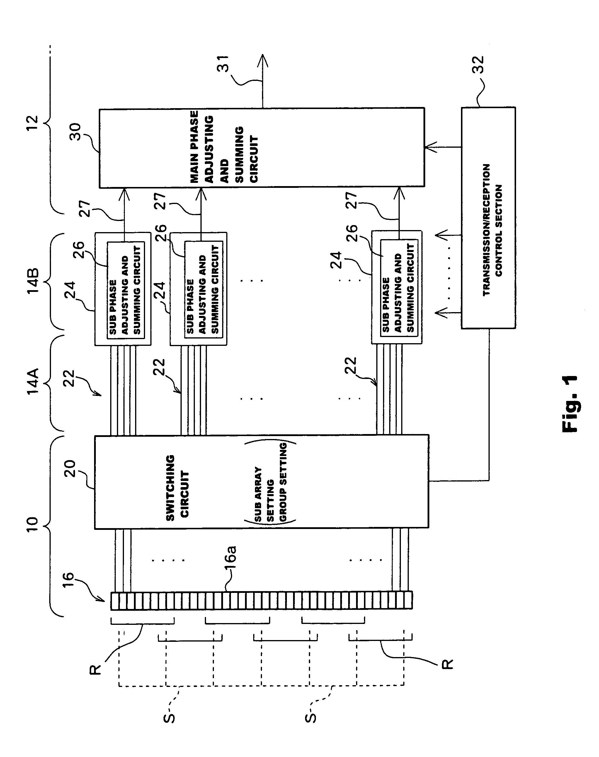
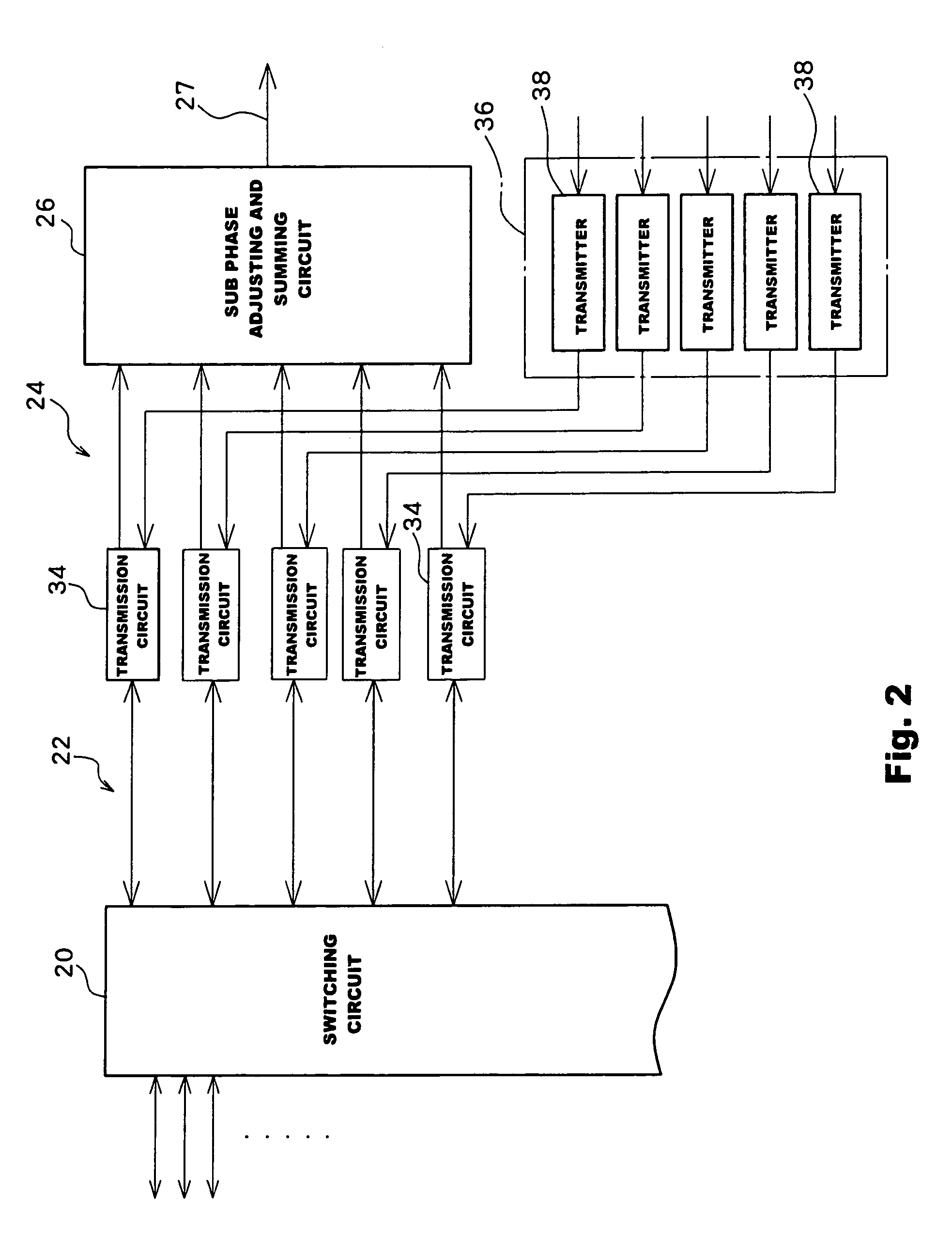
[0044]Referring first to FIG. 10, a basic structure of an ultrasound diagnosis apparatus according to a first embodiment of the present invention will be described. The ultrasound diagnosis apparatus is composed of a probe (probe unit) 240 and an apparatus body 242. The probe 240 includes a probe head 244, a probe cable 246, and a cable connector 247. The apparatus body 242 includes a transmission / reception control section 248, a receiver section 250, a signal processing module 252, an image forming section 254, and a display 256. The cable connector 247 is detachably connected to a connector (not shown) of the apparatus body 242. In the present embodiment, the cable connector 247 includes a built-in electronic circuit 249, which performs a sub phase adjusting and summing process and a transmitting signal generating process, as will be further described below with reference to FIGS....


PUM


Abstract

In an ultrasound diagnosis apparatus, a plurality of sub arrays are defined on a 2D array transducer. The sub array shape pattern of each sub array is adaptively changed in accordance with the beam scanning direction. Each sub array is composed of a plurality of groups, each of which is composed of a plurality of transducer elements. With the change of sub array shape pattern in accordance with a beam scanning direction, the group shape pattern of each group also changes. The sub array shape changes for each sub array, and a variable region is determined by the largest outer edge of the shape changed. The variable regions partially overlap with each other among a plurality of sub arrays. On a 2D array transducer, a plurality of sub arrays are always closely coupled with each other even when each sub array shape is changed.

Description

BACKGROUND OF THE INVENTION[0001]1. Field of the Invention[0002]The present invention relates to an ultrasound diagnosis apparatus for use in the field of medical treatment, and more particularly to setting of a plurality of sub arrays on an array transducer.[0003]2. Description of Related Art[0004]Ultrasound diagnosis apparatuses are used in the field of medical treatment for the purpose of diagnosing diseases of a living body (patient). More specifically, ultrasonic diagnosis apparatuses transmit an ultrasonic pulse to a living body and receive a reflected wave therefrom for forming an ultrasonic image based on a receiving signal obtained by the reflected wave received.[0005]A two-dimensional (2D) array transducer (or transducer array) is used for effecting two-dimensional scanning of ultrasonic beams to thereby form a three-dimensional echo data acquiring space within a living body. A 2D transducer is generally composed of a plurality of transducer elements arranged along X and Y...

Claims


Application Information

Patent Timeline
Patent Type & Authority Patents(United States)
IPC IPC(8): A61B8/00G01S7/52G01S7/521G01S15/89G10K11/34
CPCG01S7/52046G01S7/52079G01S15/8925G10K11/346G01S15/8927A61B8/483Y10S128/916
Inventor TAKEUCHI, HIDEKI
Owner HITACHI LTD
Why Eureka
Try Eureka