Telescopic safety arteriovenous fistula needle

a safety needle and telescopic technology, applied in the direction of intravenous devices, infusion needles, infusion syringes, etc., can solve the problems of contaminated blood or other body fluid, sharpened ends, and provocation of needlestick injuries

a safety needle and telescopic technology, applied in the direction of intravenous devices, infusion needles, infusion syringes, etc., can solve the problems of contaminated blood or other body fluid, sharpened ends, and provocation of needlestick injuries

US7322963B2Inactive Publication Date: 2008-01-29JMS SINGAPORE PTE

Image

  • Telescopic safety arteriovenous fistula needle
  • Telescopic safety arteriovenous fistula needle
  • Telescopic safety arteriovenous fistula needle

Examples


Embodiment Construction

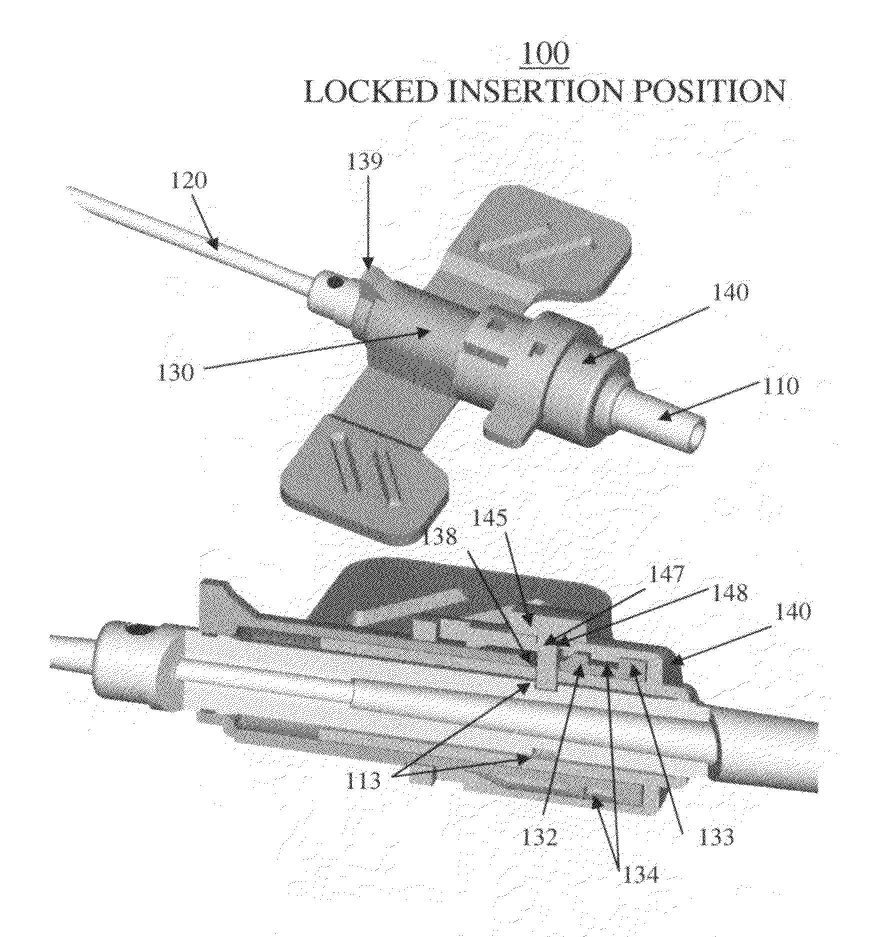
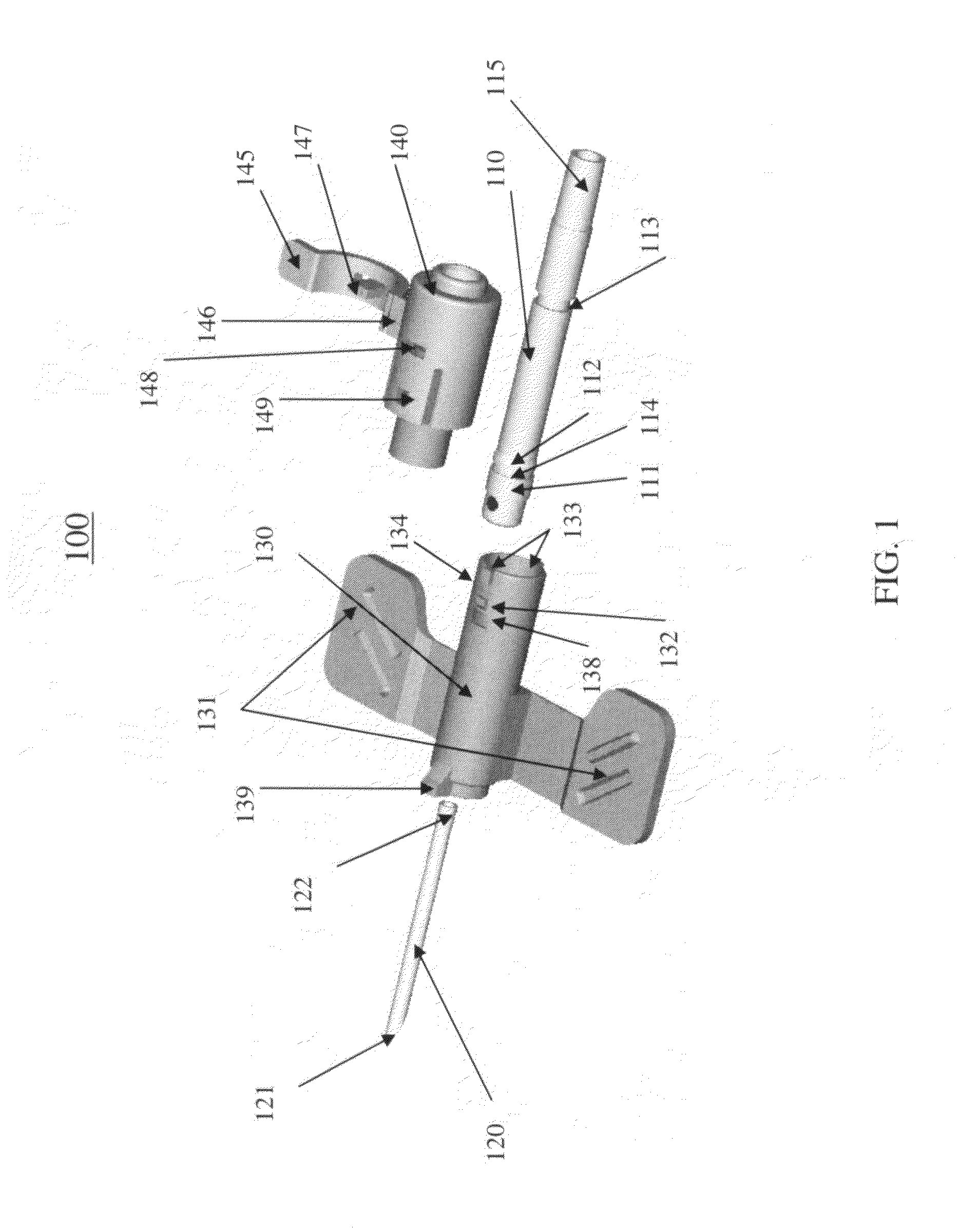
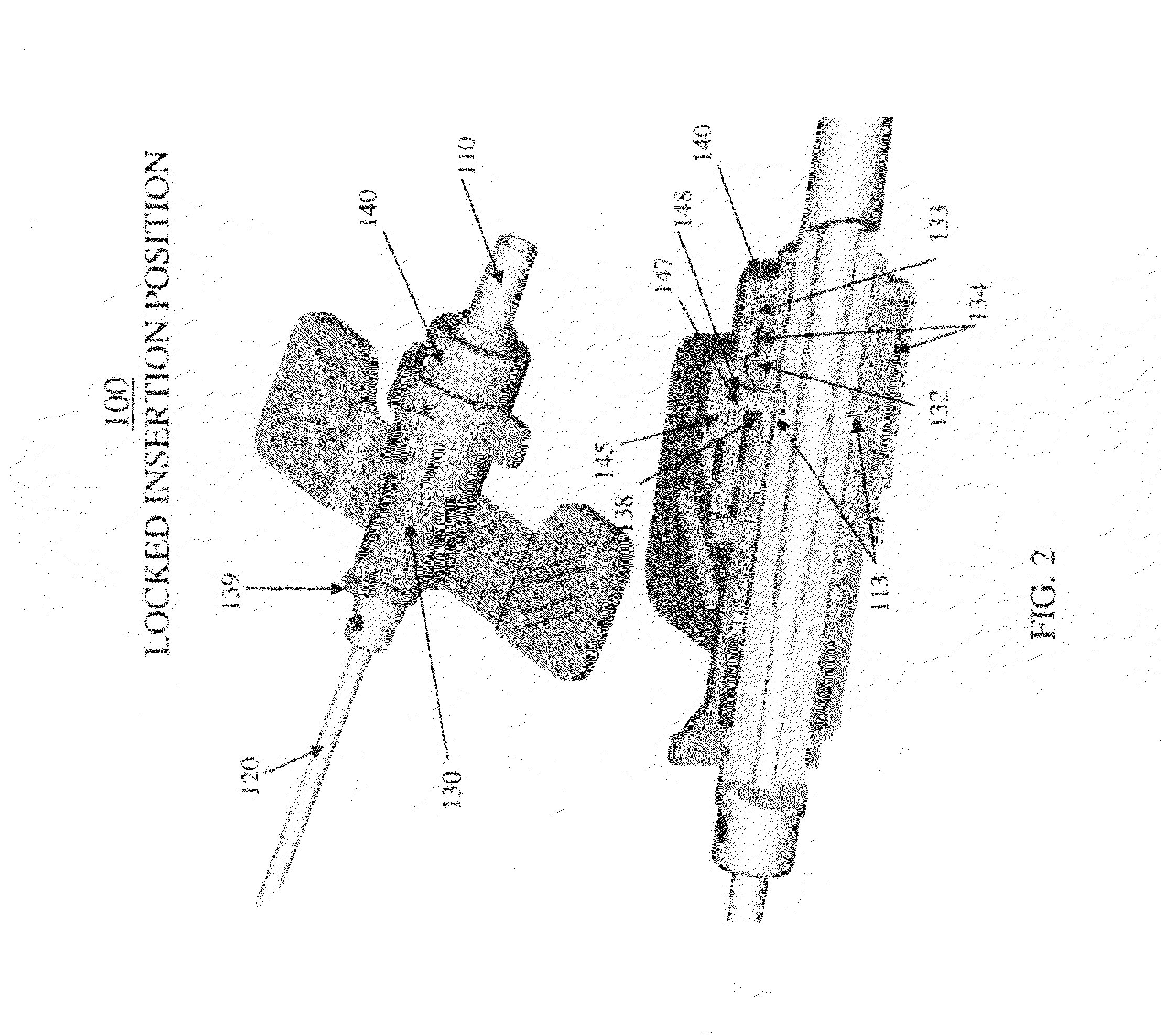
[0022]The Telescopic Safety Arteriovenous Fistula (AVF) needle assembly 100 as shown in FIG. 1, is a telescopic retractable winged safety needle device having a needle holder 110 (hereinafter referred to as a “hub”), a needle or cannula 120, a winged sheath 130, and a sleeve 140. Referring to FIGS. 1, 2, 3, and 4, the hub 110 may be tubular in shape and may be made of a polycarbonate or other polymeric material. The hub 110 secures a proximal end of the needle or cannula 120 at the distal end. The needle or cannula 120 is hollow, has a beveled edge 121 at the distal end, and may be made of stainless steel. The base 122 or proximal portion of the hollow needle 120 is fixed to and supported by the hub 110. A tube, for example a polyvinyl chloride (PVC) tube 150, is slid over the proximal end of the hub 110, providing a fluid tight seal. The hub 110 has a stopper 115 at the proximal end for tube 150 bonding. The winged sheath 130 and sleeve 140 are axially slideable on the hub 110 to f...


PUM


Abstract

A telescopic intravenous infusion set and / or blood collection assembly is provided with a safety feature for covering the used needle. The safety feature is a telescopic device including a shield with handling wings, which when placed in cooperating relationship, allows accommodation of a conventional unmodified blood collection needle affixed to a hub, and a sleeve with a locking cap. After use, the hub with the needle are pulled rearwardly into positive locking position which prevent the hub and needle from moving out of the shield thereafter. The telescopic nature of the device then allows the locked needle / hub to move rearward in relation to the shield until the shield is unreleasably locked to the sleeve. The shield provides for passage of the needle and hub from a releasable locked use position to a shielded and unreleasable locked protected position.

Description

BACKGROUND OF THE INVENTION[0001]1. Field of the Invention[0002]The present invention relates to a winged safety needle assembly and, more particularly, to a telescopic winged safety needle assembly having a winged cylindrical sheath for preventing sticking accidents from taking place when retracting the needle into the winged cylindrical sheath. Protection of the edge of the needle is achieved by unlocking and sliding the needle along the inner wall of the winged cylindrical sheath and a sleeve.[0003]2. Discussion of the Related Art[0004]Needlestick injuries are intended to be avoided by proper disposal of needles. Used needles may be recapped with the same cover that originally covered the needles before use or by similar covers or tubes before the needle is discarded. This method requires movement of the hands toward the exposed needle and may promote needlestick injuries during the recapping. In addition, needles may also be disposed of by tossing them into nearby refuse contain...

Claims


Application Information

Patent Timeline
29 Jan 2008
Publication
US7322963B2
IPC
A61M5/178; A61M5/158; A61M5/32; A61M39/10
CPC
A61M5/158; A61M5/3243; A61M39/1011
Inventors
GOH, KIM SEAH