Needle assembly

a technology of needles and parts, applied in the field of needle assemblies, can solve the problems of not providing protection for the second end of the needle at the non-patient end of the assembly, and achieve the effect of simple manufacturing and convenient operation

a technology of needles and parts, applied in the field of needle assemblies, can solve the problems of not providing protection for the second end of the needle at the non-patient end of the assembly, and achieve the effect of simple manufacturing and convenient operation

US20050240161A1Inactive Publication Date: 2005-10-27BECTON DICKINSON & CO

Image

  • Needle assembly
  • Needle assembly
  • Needle assembly

Examples


Embodiment Construction

[0019] While the present invention is satisfied by embodiments in many different forms, there is shown in the drawings and will herein be described in detail, the preferred embodiments of the invention, with the understanding that the present disclosure is to be considered as examplary of the principles of the invention and is not intended to limit the invention to the embodiments illustrated. Various other embodiments will be apparent to and readily made by those skilled in the art without departing from the scope and spirit of the invention. The scope of the invention will be measured by the appended claims and their equivalents.

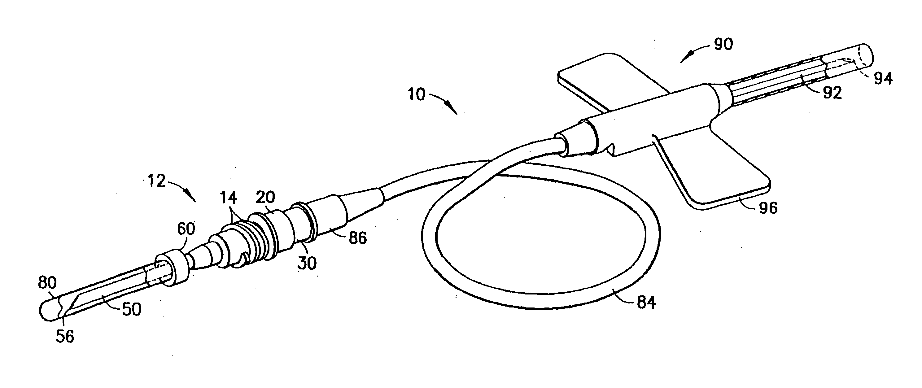
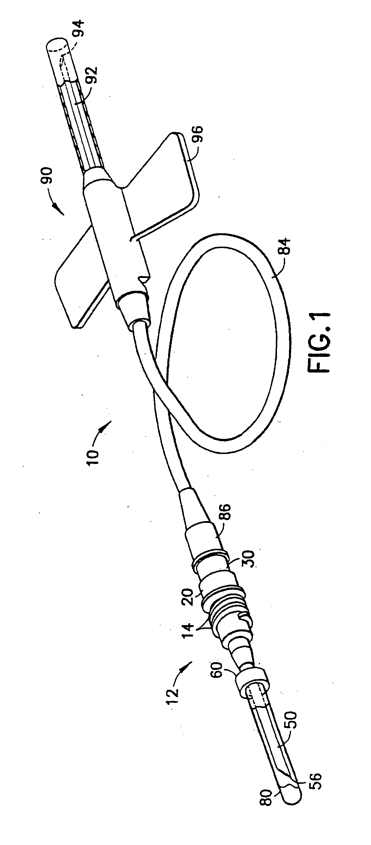
[0020] Referring to the drawings in which like reference characters refer to like parts throughout the several views thereof, FIG. 1 illustrates a blood collection set in accordance with the present invention and the related features. The present invention is generally described in terms of a blood collection set, and encompasses such a blood collection s...


PUM


Abstract

A blood collection set including a non-patient needle assembly interconnected with an intravenous needle assembly through tubing is provided. The non-patient needle assembly includes a hub assembly adapted for mounting with a blood collection set, and an internal blunting member including a blunted tip. The non-patient needle assembly further includes an external cannula concentric with the internal blunting member and including a non-patient puncture tip adjacent the blunted tip. The external cannula is axially displaceable with respect to the hub assembly between a first retracted position in which the non-patient puncture tip extends beyond the blunted tip and a second activated position in which blunted tip extends beyond the non-patient puncture tip.

Description

RELATED APPLICATIONS [0001] This application is a divisional of U.S. patent application Ser. No. 10 / 173,928 filed June 17, 2002, which in turn claims priority to U.S. Provisional Patent Application No. 60 / 377,399 filed May 2, 2002.BACKGROUND OF THE INVENTION [0002] 1. Field of the Invention [0003] The present invention relates to needle assemblies having a blunting element for safe and convenient handling. More particularly, the present invention relates to a non-patient needle assembly which includes a blunting element for the non-patient needle for use in connection with a blood collection set. [0004] 2. Description of Related Art [0005] Disposable medical devices having piercing elements are typically used for administering a medication or withdrawing a fluid, such as blood collecting needles, fluid handling needles and assemblies thereof. Current medical practice requires that the fluid containers and needle assemblies used in such systems be inexpensive and readily disposable. ...

Claims


Application Information

Patent Timeline
27 Oct 2005
Publication
US20050240161A1
IPC
A61B5/15; A61M5/158; A61M5/32
CPC
A61M2005/3212; A61B5/1444; A61B5/15003; A61B5/150389; A61B5/150519; A61B5/150572; A61B5/150641; A61B5/150717
Inventors
CRAWFORD, JAMIESON WILLIAM MCLEAN