Electrochromic devices with thin bezel-covered edge

a technology of optical components and bezels, applied in the field of optical components, to achieve the effect of maintaining uniform coloration of ec mirrors and minimizing the contribution of transparent conductors to hu

Inactive Publication Date: 2008-01-29
GENTEX CORP
View PDF26 Cites 387 Cited by
  • Summary
  • Abstract
  • Description
  • Claims
  • Application Information

AI Technical Summary

Benefits of technology

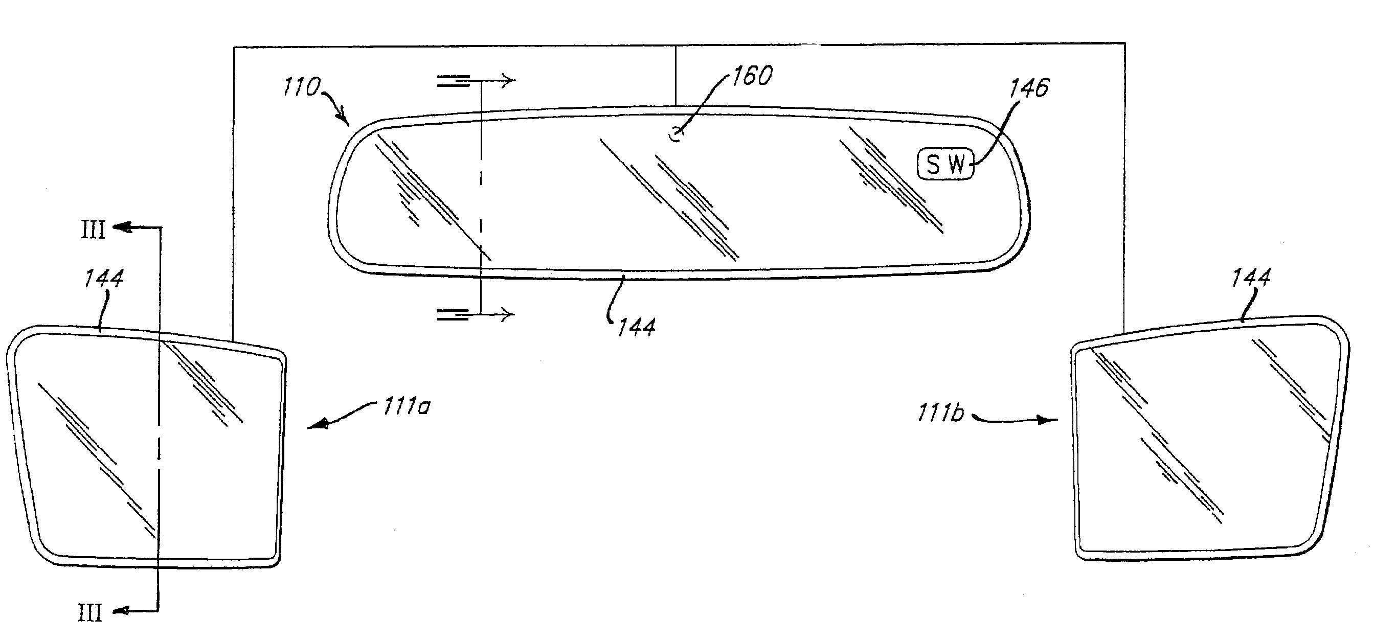
[0012]In at least one embodiment, an electro-optic element is provided that comprises front and rear substrates that have substantially parallel perimeters aside from portions of the edges that are recessed or provided with tab portions for facilitating contact to associated electrically conductive coatings. In at least one related embodiment, the “second surface” of the front substrate is provided with a substantially transparent electrically conductive layer, or layers, of highly electrically conductive material. In at least one additional embodiment, the “third surface” of the rear substrate is provided with a highly electrically conductive layer, or layers; the second surface of the front substrate may also have a highly electrically conductive layer, or layers. In at least one additional related embodiment, the element is attached to a carrier plate having an integral bezel only proximate an edge associated with the contacts to the electrically conductive coatings. In yet at least one additional embodiment, an element is provided with an at least partially opaque coating around the perimeter of the front substrate, on either the first or second surface, such that the associated seal is not visible. In at least one related embodiment, the perimeter coating has a reflectivity that is substantially matched to the reflectivity of the remainder of the reflective element. In another related embodiment, the perimeter coating is a spectral filter that substantially blocks ultra-violate and, or, infrared light rays from impinging upon the associated seal; the spectral filter may be incorporated within the corresponding substrate as opposed to being a coating on the first or second surface thereof. If a coating such as a reflective material is applied around the perimeter of the mirror on the first or second surface to mask the seal and/or contact area, the reflected color of the coating becomes important. Typically it is desirable to produce a reflective color that is neutral or substantially uniform in the visible spectrum or a reflective color that matches the color of the remainder of the mirror element in the clear or bleached state. When this coating is applied to the second surface over the transparent conductor, the apparent color of the coating when viewed from the front is influenced by the optical properties of the transparent conductor. This color can be controlled by the selection of the materials and thicknesses of the materials used to produce the transparent conductor. If color neutrality is desired, a color suppression layer can be used when depositing the transparent conductor or a very thick layer of conductor that is inherently low in color (about 3 wave or above) can be used. Alternatively, the perimeter coating can be applied to the second surface of the first substrate prior to deposition of the transparent conductor. All of the above techniques for minimizing the contribution the transparent conductor has on hue, also apply if the

Problems solved by technology

While the above-described structure is readily manufacturable, styling concerns have arisen wi

Method used


Image

  • Electrochromic devices with thin bezel-covered edge
  • Electrochromic devices with thin bezel-covered edge
  • Electrochromic devices with thin bezel-covered edge

Examples


Embodiment Construction

[0075]Reference will now be made in detail to the present preferred embodiments of the invention, examples of which are illustrated in the accompanying drawings. Wherever possible, the same reference numerals will be used throughout the drawings to refer to the same or like parts. In the drawings, the depicted structural elements are not to scale and certain components are enlarged relative to the other components for purposes of emphasis and understanding.

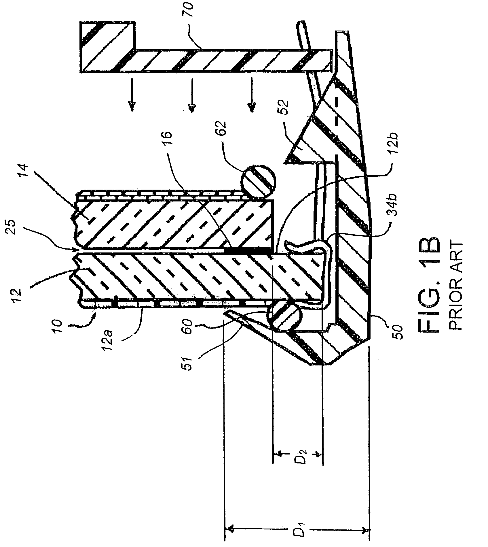
[0076]As described above, the electro-optic mirror subassemblies provide the advantage of a reduced bezel front lip width of preferably about 4 mm or less, and more preferably less than about 3.6 mm, while still extending over all of the seal width, and preferably extending about 0.5 mm beyond an innermost edge of the seal so as to sufficiently obscure the view of the seal. According to some aspects of the present invention, a bezel may not even be utilized due to other inventive techniques for obscuring the view of the seal throu...


PUM


Abstract

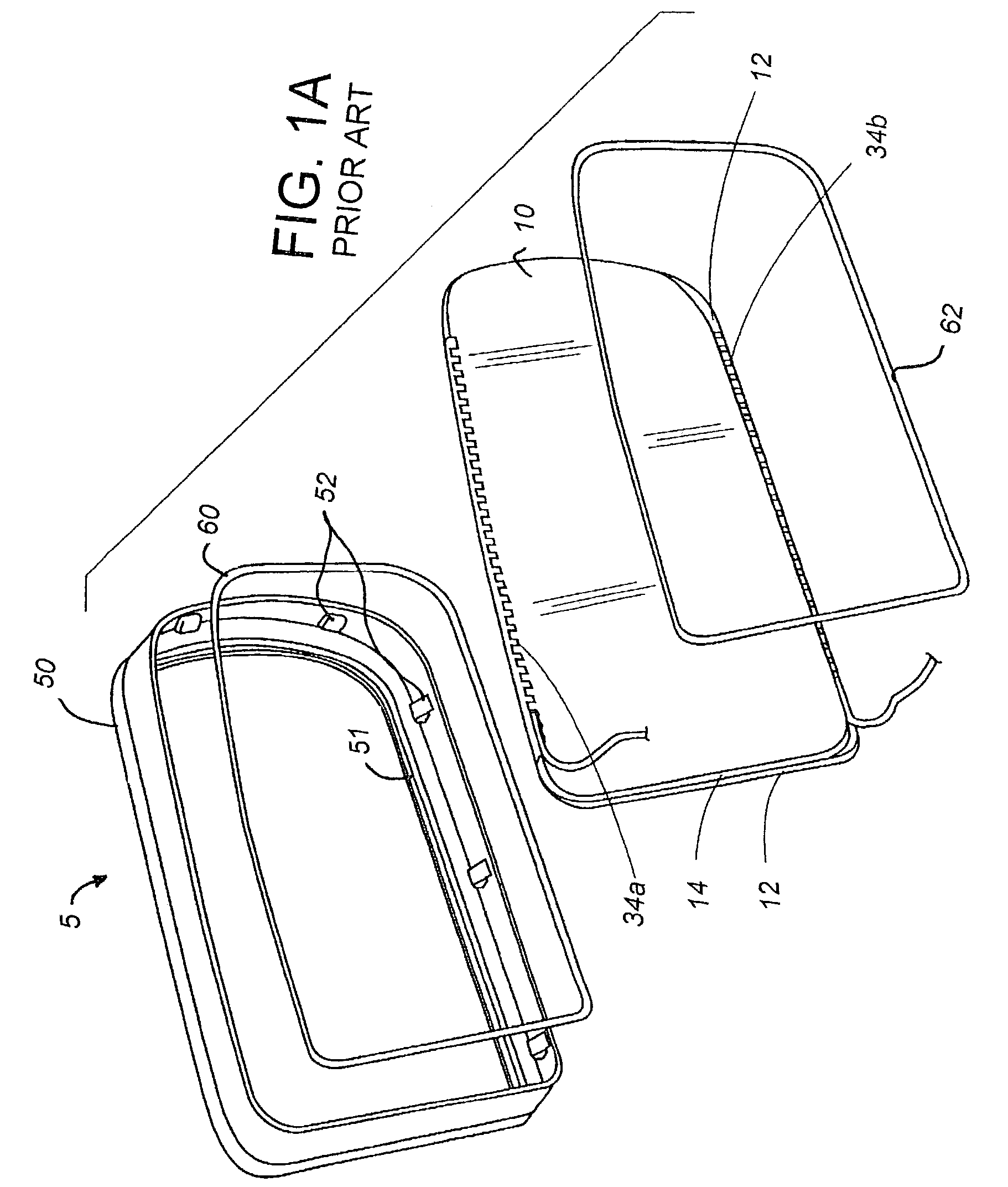
A mirror includes an electro-optic mirror subassembly, and a thin-profiled bezel attached around a perimeter of the electrochromic mirror subassembly. The electro-optic mirror subassembly is supported on a carrier by an adheringly bonded heater and foam tape in a laminar arrangement. The bezel may be bonded to an edge of the front surface of the front element of the electro-optic mirror subassembly, and/or may be bonded and/or interlockingly mechanically attached to an edge of the carrier. Alternatively, the bezel can be a strip of paint or thin coating material. The bezel can be molded in place, or can be pre-molded and elastically stretched to permit assembly. In one form, the bezel includes a laterally-extending fin that prevents seeing past the bezel into the inside of a mirror housing. In at least one embodiment, the assembly has no bezel or only a bezel on one edge.

Description

CROSS-REFERENCE TO RELATED APPLICATION[0001]This is a continuation-in-part of U.S. patent application Ser. No. 10 / 260,741, filed Sep. 30, 2002 now U.S. Pat. No. 7,064,882, entitled ELECTROCHROMIC DEVICES HAVING NO POSITIONAL OFFSET BETWEEN SUBSTRATES, and U.S. patent application Ser. No. 09 / 884,717, filed Jun. 19, 2001, entitled COUPLED ELECTROCHROMIC COMPOUNDS WITH PHOTOSTABLE DICATION OXIDATION STATES, now U.S. Pat. No. 6,560,004, which is a continuation of U.S. patent application Ser. No. 09 / 350,879, filed on Jul. 9, 1999, which is now U.S. Pat. No. 6,249,369, the entire contents of which are incorporated herein by reference.BACKGROUND OF THE INVENTION[0002]The present invention generally relates to electro-optic devices and apparatus incorporating these devices. More particularly, the invention relates to electro-optic devices used in architectural windows or vehicle rearview mirrors.[0003]Electro-optic elements are used in a variety of applications including light shutters, var...

Claims


Application Information

Patent Timeline
IPC IPC(8): G02F1/15G02F1/153C09K9/02G02F1/1503
CPCC09K9/02G02F1/1521G02F1/153G02F2001/1502G02F2001/1512G02F1/1503G02F2001/15145
Inventor TONAR, WILLIAM L.BAUER, FREDERICK T.ARNOLD, JOHN W.CAMMENGA, DAVID J.CARTER, JOHN W.BUSSCHER, BRADLEY L.FOGG, JEREMY A.ANDERSON, JOHN S.
Owner GENTEX CORP
Why Eureka
Try Eureka