Radio transmitting apparatus and radio transmission method

a technology of radio transmission apparatus and receiver, which is applied in the direction of power management, electromagnetic wave modulation, wireless commuication services, etc., can solve the problems of modulated signal reception quality decline, large quantization error of analog/digital converter in the receiving apparatus, etc., and achieve the effect of reducing pilot symbol and data symbol quantization error and improving reception quality

Active Publication Date: 2008-01-29
REDWOOD TECHNOLOGIES LLC
View PDF12 Cites 12 Cited by
  • Summary
  • Abstract
  • Description
  • Claims
  • Application Information

AI Technical Summary

Benefits of technology

[0008]It is an object of the present invention to provide a radio transmitting apparatus and radio transmission method that enable reception quality to be improved by reducing pilot symbol and data symbol quantization error in a system in which the number of simultaneously transmitted modulated signals is changed according to the propagation environment and so forth.

Problems solved by technology

However, with a system in which the number of modulated signals transmitted simultaneously is changed according to the radio wave propagation environment and so forth, the received signal level also changes in accordance with a change of the number of transmitting antennas (that is, the number of transmit modulated signals), and therefore the quantization error of an analog / digital converter in the receiving apparatus may become large.
As this quantization error greatly affects the channel estimation precision and information data error rate, the modulated signal reception quality falls.

Method used


Image

  • Radio transmitting apparatus and radio transmission method
  • Radio transmitting apparatus and radio transmission method
  • Radio transmitting apparatus and radio transmission method

Examples


embodiment 1

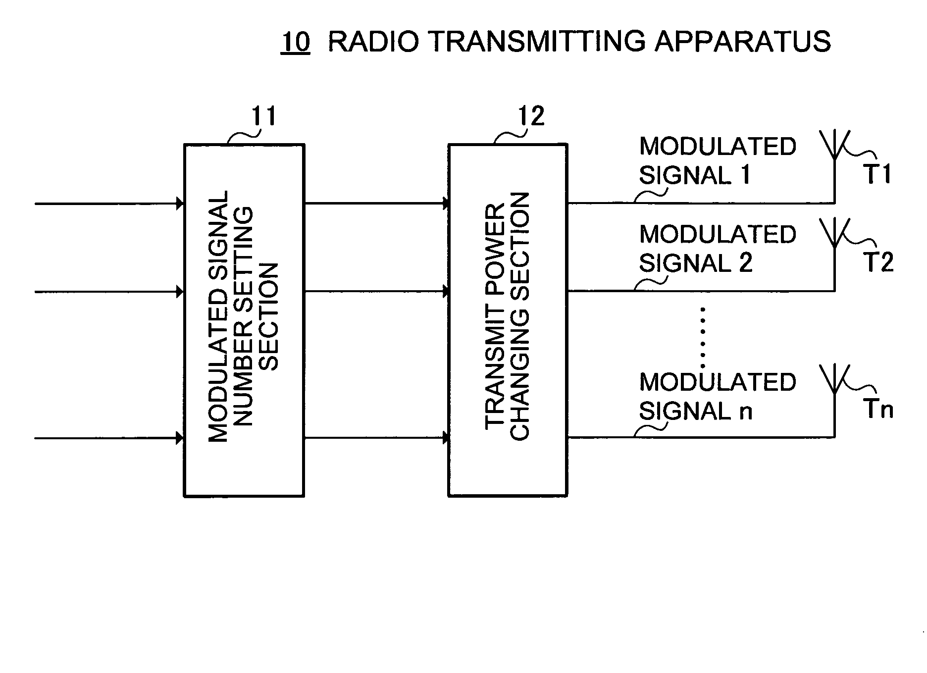
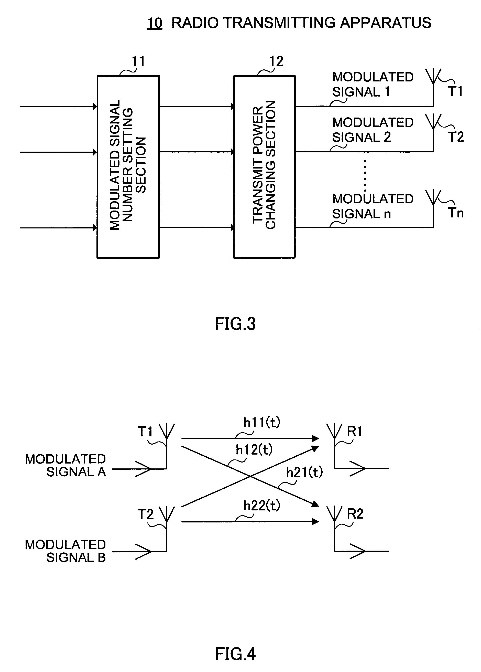
[0069]A particular feature of this embodiment is that the transmit power of a pilot symbol contained in a modulated signal is changed according to the number of antennas that simultaneously transmit modulated signals (that is, the number of modulated signals). By this means, pilot symbol quantization error in a receiving apparatus can be reduced.

[0070]Specifically, when the number of simultaneously transmitted modulated signals is changed, the combined power (that is, the dynamic range) of data symbols contained in each modulated signal changes on the receiving side, and therefore pilot symbol transmit power is changed so as to match this combined data symbol dynamic range. Actually, the signal point arrangement when a pilot symbol is formed is changed so that the ratio of data symbol transmit power to pilot symbol transmit power changes according to the number of transmit modulated signals.

(1) Principle

[0071]First, the principle of this embodiment will be explained.

[0072]A case wil...

embodiment 2

[0135]A particular feature of this embodiment is that, when the number of antennas that transmit modulated signals (that is, the number of modulated signals) changes, the average transmit power of each modulated signal is changed. By this means, it is possible to reduce the quantization error of each modulated signal especially immediately after the number of transmitting antennas is switched.

(1) Principle

[0136]First, the principle of this embodiment will be explained.

[0137]FIG. 19 and FIG. 20 show variation of a general receive waveform when the number of modulated signals transmitted from a plurality of antennas is switched. FIG. 19 shows a case in which the number of modulated signals transmitted (that is, the number of transmitting antennas) is switched from two to four, and FIG. 20 shows a case in which the number of modulated signals transmitted (the number of transmitting antennas) is switched from four to two. As is clear from FIG. 19, when switching is performed so that the...

embodiment 3

[0160]In this embodiment, a specific example will be described of a case in which the method whereby pilot symbol and modulated signal transmit power is changed according to the number of antennas that simultaneously transmit modulated signals (the number of modulated signals) described in Embodiments 1 and 2 is applied to an actual radio system. Specifically, in this embodiment, a method is described whereby gain control is stabilized by lengthening the gain control time of AGC (Automatic Gain Control) in a receiving apparatus.

[0161]In a typical receiving apparatus, when input of a signal to the receiving apparatus is detected, AGC is performed in accordance with the input signal level so that the received signal is within the dynamic range of the A / D converter that performs analog / digital conversion. There are two possible methods of stabilizing gain control by means of AGC, as follows:[0162](i) Stabilizing the dynamic range of a signal input to the receiving apparatus[0163](ii) L...


PUM


Abstract

A radio transmitting apparatus that has a plurality of antennas and changes the number of modulated signals transmitted simultaneously according to the propagation environment and so forth. A transmission power changing section 12 of a radio transmitting apparatus of the present invention adjusts the pilot symbol signal level so as to match the data symbol composite signal level according to the number of transmit modulated signals set by a modulated signal number setting section 11. By this means, the operating range of received pilot symbols and the operating range of received data symbols become approximately the same on the receiving side, enabling pilot symbol quantization error to be reduced. As a result, the precision of radio wave propagation environment estimation, time synchronization, and frequency offset estimation using pilot symbols improves, and consequently data reception quality improves.

Description

TECHNICAL FIELD [0001]The present invention relates in particular to a radio transmitting apparatus and radio transmission method whereby modulated signals are transmitted using a plurality of antennas.BACKGROUND ART [0002]Heretofore, methods have been proposed whereby the amount of transmitted information is increased by transmitting different modulated signals from a plurality of antennas, and separating and modulating modulated signals transmitted simultaneously from individual antennas on the receiving side, as with the transmission method known as MIMO (Multi Input Multi Output) described in “Proposal for an SDM-COFDM System for Wideband Mobile Communications Achieving 100 Mbit / s by Means of MIMO Channels” (IEICE Technical Report RCS-2001-135, October 2001), for example.[0003]This method will be explained briefly. A case will be considered in which, as shown in FIG.1, a modulated signal A and modulated signal B are simultaneously transmitted from two antennas T1 and T2 respecti...

Claims


Application Information

Patent Timeline
Patent Type & Authority Patents(United States)
IPC IPC(8): H04Q7/00H04B7/005H04B7/04H04B17/40H04J11/00H04J99/00H04W52/42
CPCH04L27/2649H04W52/42H04L1/0001H04L27/2627
Inventor KOBAYASHI, KIYOTAKAMURAKAMI, YUTAKAORIHASHI, MASAYUKI
Owner REDWOOD TECHNOLOGIES LLC
Why Eureka
Try Eureka