Eureka AIR delivers breakthrough ideas for toughest innovation challenges, trusted by R&D personnel around the world.

Radiation computed tomography apparatus and tomographic image producing method

a computed tomography and computed tomography technology, applied in tomography, material analysis using wave/particle radiation, instruments, etc., can solve the problems of poor data continuity, adverse effect of tomographic image quality, poor data continuity, etc., to improve the image improve the quality of tomographic imag

Inactive Publication Date: 2008-01-29
GE MEDICAL SYST GLOBAL TECH CO LLC
View PDF13 Cites 13 Cited by
  • Summary
  • Abstract
  • Description
  • Claims
  • Application Information

AI Technical Summary

Benefits of technology

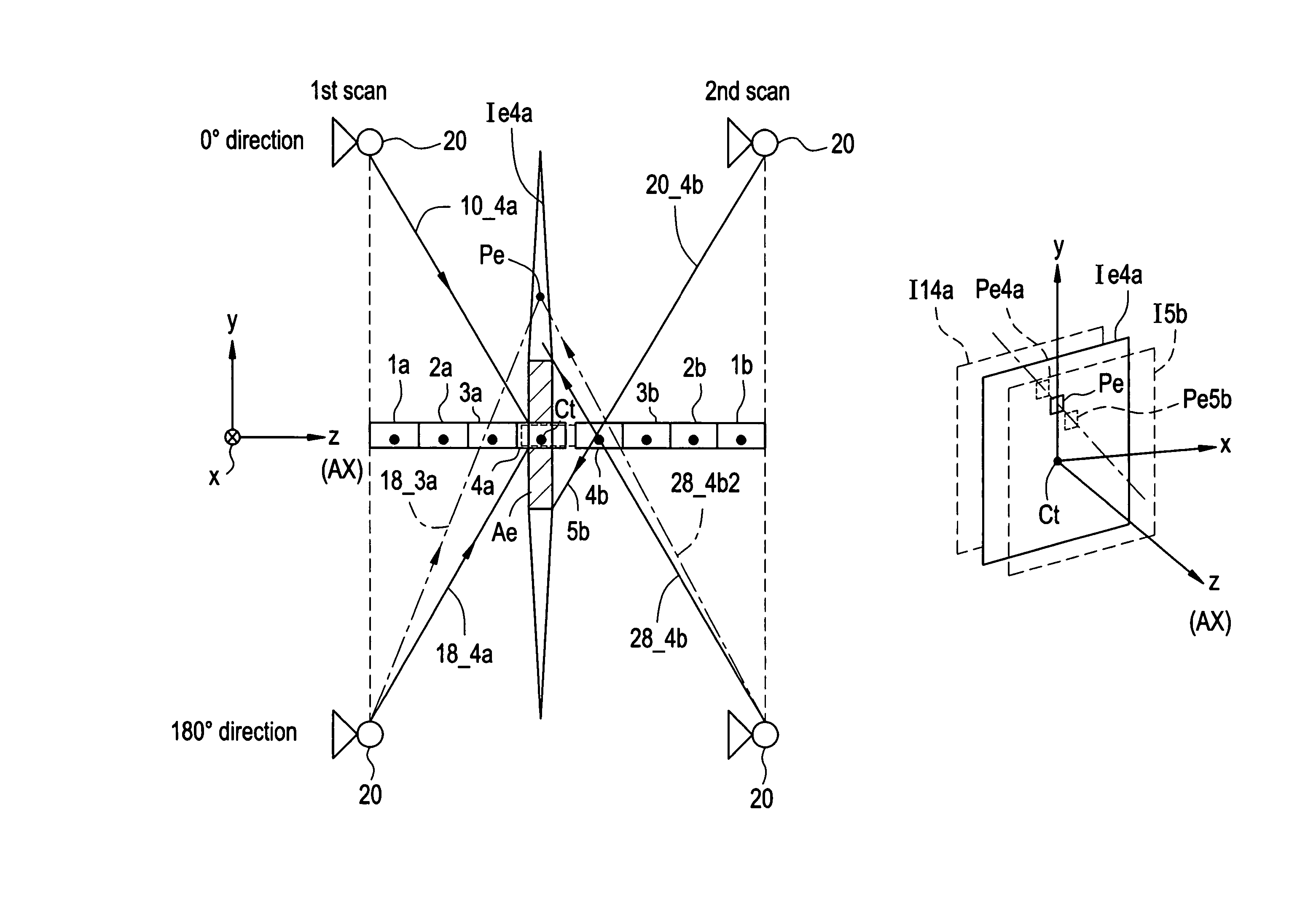
[0010]It is an object of the present invention to provide a radiation computed tomography apparatus (radiation CT apparatus) that can improve the image quality of a tomographic image at a predefined image production position in a subject's axis direction in tomographic image reconstruction by axial scanning. It is also an object of the present invention to provide a tomographic image producing method for use in the radiation CT apparatus, which method can improve the image quality of a tomographic image at an image production position.
[0017]Therefore, the present invention provides a radiation computed tomography apparatus that can improve the image quality of a tomographic image at a predefined image production position in a subject's axis direction in tomographic image reconstruction by axial scanning. The present invention also provides a tomographic image producing method for use in the radiation CT apparatus, which method can improve the image quality of a tomographic image at an image production position.

Problems solved by technology

Therefore, in an axial scan, data continuity is poor between a tomographic image acquired in a scan at one position in the axis direction and that acquired in another scan at another position.
Such poor data continuity results in disadvantages such as that there is an adverse effect on the image quality of a tomographic image obtained by multiplanar reformation (MPR) using a plurality of other tomographic images orthogonal to the axis direction obtained by the cone BP process.
An example of the disadvantages is insufficient smoothness in the MPR image obtained by the multiplanar reformation, in which banding artifacts occur in a portion corresponding to the border between the scans.

Method used


Image

  • Radiation computed tomography apparatus and tomographic image producing method
  • Radiation computed tomography apparatus and tomographic image producing method
  • Radiation computed tomography apparatus and tomographic image producing method

Examples


Embodiment Construction

[0029]Embodiments of the present invention will now be described with reference to the accompanying drawings. Radiation in the present invention includes X-rays. The following description will be made on an X-ray CT apparatus as an example of the radiation CT apparatus.

[0030]Apparatus Configuration

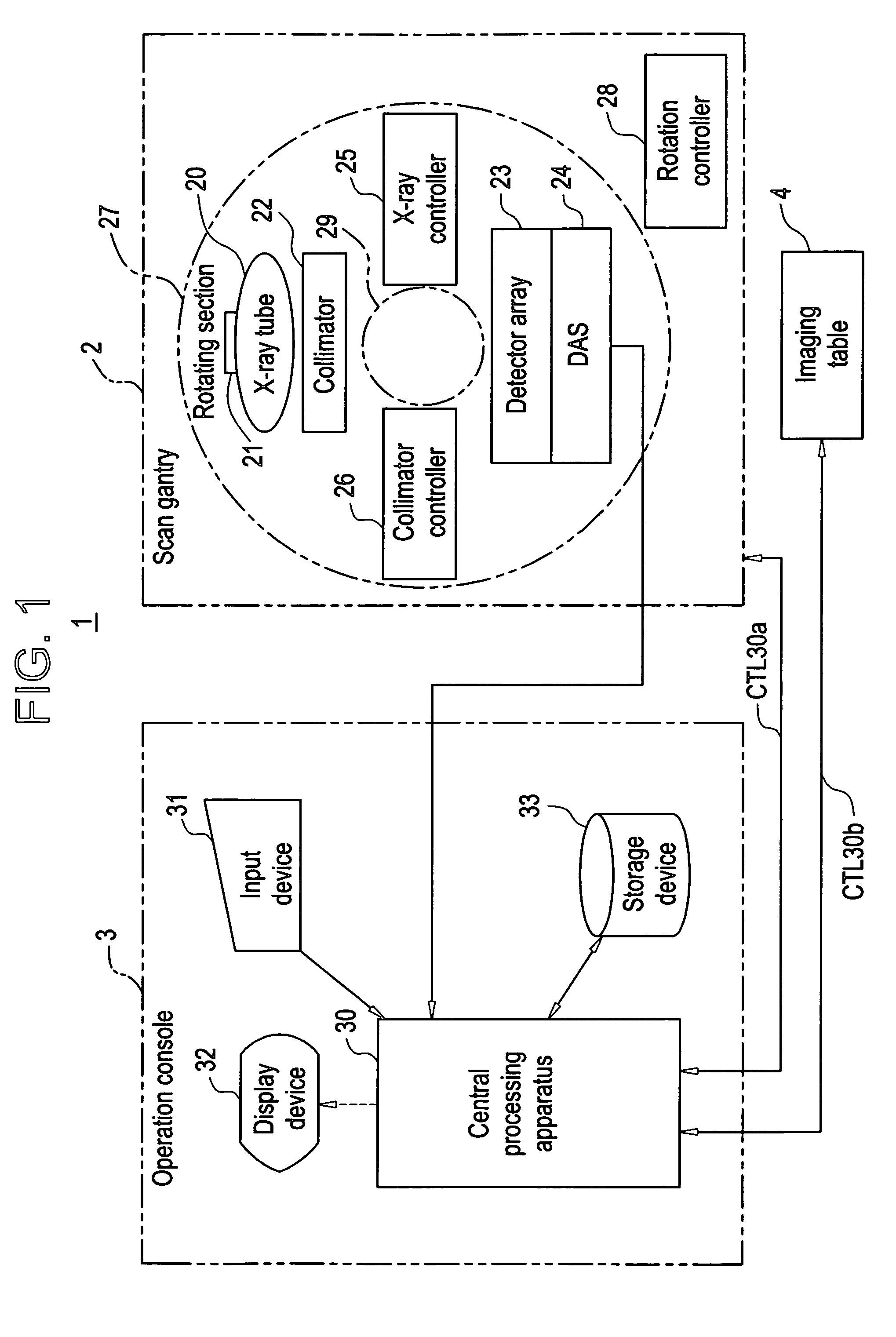
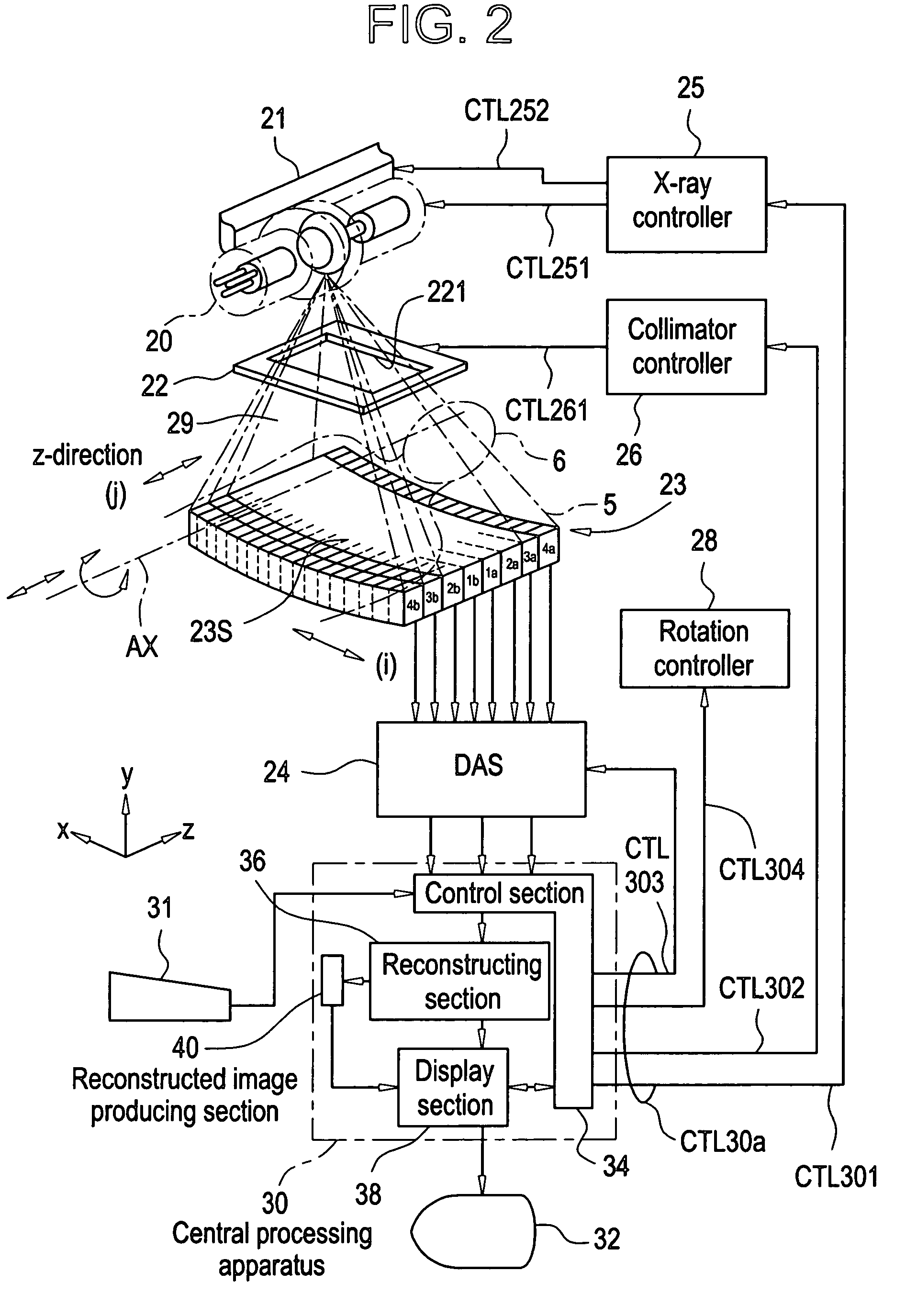
[0031]FIG. 1 shows the apparatus configuration of an embodiment of an X-ray CT apparatus in accordance with the present invention, and FIG. 2 shows the configuration of a main portion in the X-ray CT apparatus shown in FIG. 1. The X-ray CT apparatus I shown in FIG. 1 is an embodiment of the radiation computed tomography apparatus in the present invention.

[0032]As shown in FIG. 1, the X-ray CT apparatus 1 in accordance with the present embodiment comprises a scan gantry 2, an operation console 3, and an imaging table 4.

[0033]The scan gantry 2 comprises an X-ray tube 20, a moving section 21, a collimator 22, a detector array 23, a data acquisition system (DAS) 24, an X-ray controller 25, a c...


PUM


Abstract

A computed tomography (CT) imaging system for improving the image quality of a tomographic image at a predefined image production position in a subject's axis direction in tomographic image reconstruction by axial scanning. The CT system includes an X-ray tube and a detector array configured to conduct a plurality of scans for detecting X-rays passing through a region to be examined around an axis AX of the region to be examined at different positions along the subject's axis Ax direction; and for each of the plurality of scans, and a reconstructing section configured to calculate and reconstruct data for tomographic images of the region to be examined at a position corresponding to a detector row in the axis direction based on detected data acquired in that scan, and combine the data for the plurality of reconstructed tomographic images to generate data for a combined tomographic image at the position corresponding to the detector row.

Description

CROSS REFERENCE TO RELATED APPLICATIONS[0001]This application claims the benefit of Japanese Application No. 2003-115407 filed Apr. 21, 2003.BACKGROUND OF THE INVENTION[0002]The present invention relates to a radiation computed tomography apparatus (referred to as a radiation CT apparatus hereinbelow) and a tomographic image producing method for calculating a tomographic image of a subject from radiation projection data on the subject.[0003]Known radiation CT apparatuses include an X-ray CT apparatus employing X-rays as radiation, for example. Known X-ray CT apparatuses include an apparatus comprising a plurality of X-ray detectors arranged in a two-dimensional manner. The plurality of X-ray detectors are disposed to have a width in a direction along a predefined axis with respect to a subject. Since rows of X-ray detectors are formed in the axis direction in the predefined width, the X-ray detectors arranged in a two-dimensional manner are generally referred to as a multi-row detec...

Claims


Application Information

Patent Timeline
IPC IPC(8): G01N23/00A61B6/03G01N23/04G06T11/00
CPCA61B6/032A61B6/5205G06T11/005G01N23/046G01N2223/612G01N2223/419A61B6/03
Inventor MORIKAWA, KOTOKOHAGIWARA, AKIRA
Owner GE MEDICAL SYST GLOBAL TECH CO LLC
Why Eureka
Eureka Blog
Learn More