Oscillating micro-mechanical sensor of angular velocity

a micro-mechanical sensor and angular velocity technology, applied in the direction of acceleration measurement using interia force, turn-sensitive devices, instruments, etc., can solve the problems of quadrature signals, hundreds of times the strength of full, poor dimensional accuracy of structures, etc., and achieve reliable and efficient measurement

Active Publication Date: 2008-02-05
MURATA MFG CO LTD
View PDF15 Cites 17 Cited by
  • Summary
  • Abstract
  • Description
  • Claims
  • Application Information

AI Technical Summary

Benefits of technology

[0014]The object of the invention is to provide such an improved oscillating sensor of angular velocity, enabling reliable and efficient measuring particularly in compact oscillating solutions for sensors of angular velocity, and in which an electrostatic quadrature signal compensation is implemented, that is particularly well suited for micro-mechanical rotary oscillating sensors of angular velocity, in comparison with prior art solutions.

Problems solved by technology

The biggest problem concerning micro-mechanical oscillating sensors of angular velocity is the so called quadrature signal, which is caused by poor dimensional accuracy of the structures.
Resonators manufactured in the methods of micro-mechanics may have faulty tolerance in the orthogonality of their directions of motion, which gives rise to a signal, called a quadrature signal, which, at worst, is even hundreds of times the strength of the full scale indication of the angular velocity signal.
Since it is considerably much larger than the signal to be measured, it limits, however, the dynamics of the signal.
In addition, the biggest disadvantage of the quadrature signal is the fact that it, due to phase shifts of the electronic signals, unless compensated, impairs the stability of the null point of the sensor.
This way of compensation is not very useful, since it merely shifts the stringent phase stability requirements of the electronics from the demodulation to the compensation block.
The structures according to prior art described above are not, however, suitable for application in sensors of angular velocity, wherein the primary motion is one of rotary oscillation.

Method used


Image

  • Oscillating micro-mechanical sensor of angular velocity
  • Oscillating micro-mechanical sensor of angular velocity
  • Oscillating micro-mechanical sensor of angular velocity

Examples


Embodiment Construction

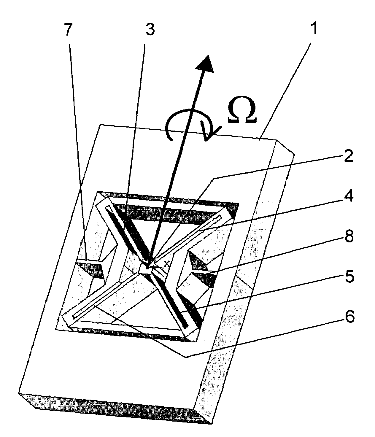
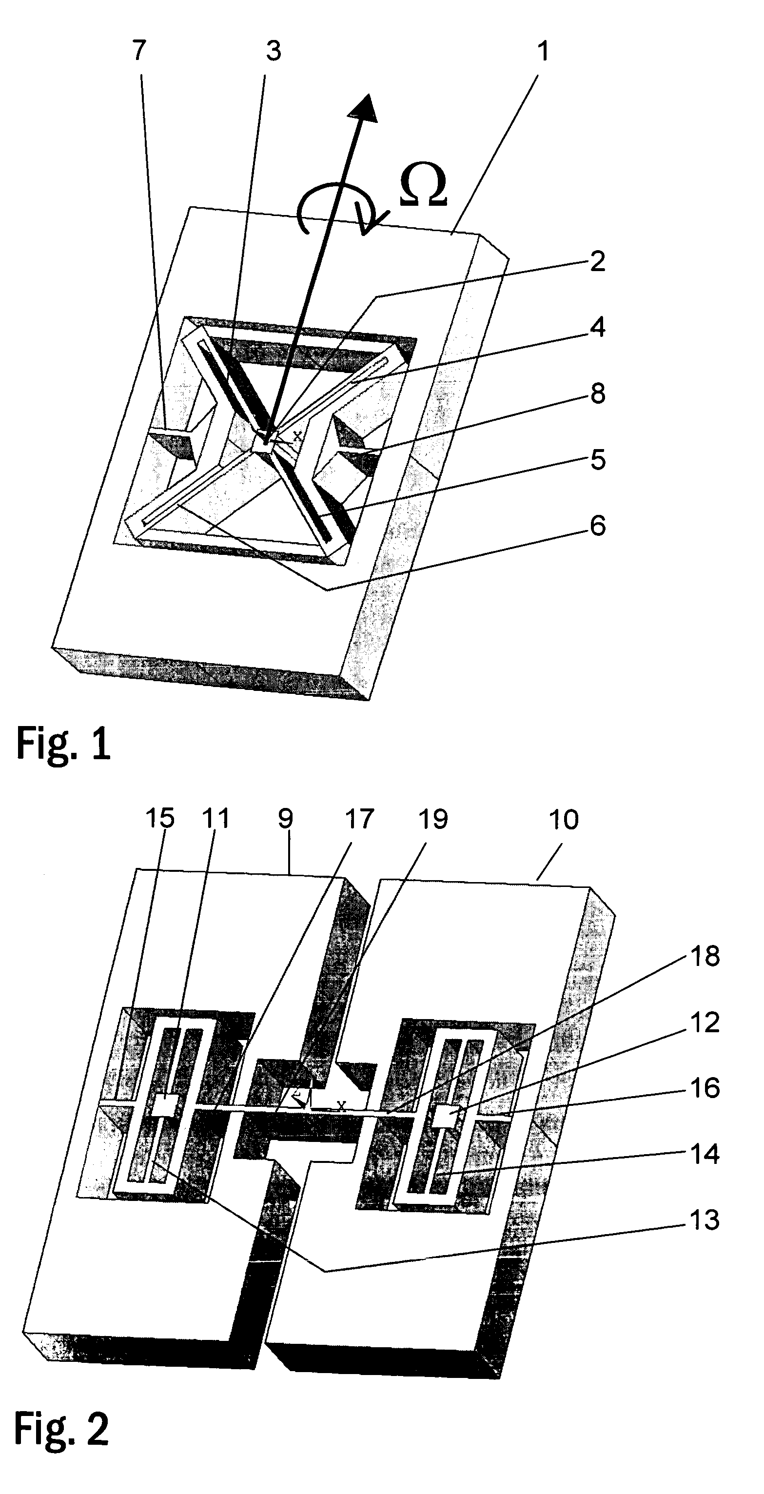
[0048]In the oscillating sensor of angular velocity according to the present invention, the primary motion, which has to be generated, is a rotary oscillation of at least one seismic mass and an associated movable electrode about an axis perpendicular to the plane of the disk. In addition to the primary motion, the seismic mass possesses a second degree of freedom in relation to a detection axis perpendicular to the primary motion.

[0049]At least one pair of electrodes is provided underneath or above at least one edge of the seismic mass, which pair of electrodes, together with the surface of the mass, form two capacitances. These capacitances vary as a function of the angle of rotation in the primary motion, positively in one of the electrodes, negatively in the other. The electrodes of the pair can be positioned equidistant on each side of the detection axis. A voltage of equal magnitude in relation to the potential of the mass can be applied to both electrodes of the pair, accompl...


PUM


Abstract

The present invention relates to measuring devices used in measuring angular velocity and, more specifically, to oscillating micro-mechanical sensors of angular velocity. In the sensors of angular velocity according to the present invention, at least one pair of electrodes is provided in association with an edge of a seismic mass (1), (9), (10), (20), (30), (31), which pair of electrodes together with the surface of the mass (1), (9), (10), (20), (30), (31) form two capacitances such, that one of the capacitances of the pair of electrodes will increase and the other capacitance of the pair of electrodes will decrease as a function of the angle of rotation in the primary motion of the mass (1), (9), (10), (20), (30), (31). The structure of a sensor of angular velocity according to the present invention enables reliable and efficient measuring particularly in solutions for compact oscillating micro-mechanical sensors of angular velocity.

Description

FIELD OF THE INVENTION[0001]The invention relates to measuring devices for use in measuring angular velocity and, more specifically, to oscillating micro-mechanical sensors of angular velocity. The invention aims at providing an improved sensor structure enabling reliable and efficient measuring, particularly in compact oscillating micro-mechanical angular velocity sensor solutions.BACKGROUND OF THE INVENTION[0002]Measuring based on an oscillating sensor of angular velocity has proved to have a simple principle and to provide a reliable way of measuring angular velocity. A certain known primary motion is being generated and maintained in the oscillating sensor of angular velocity. The movement, which the sensor is designed to measure, is detected as a deviation of the primary motion.[0003]An external angular velocity affecting the sensor in a direction perpendicular to the direction of motion of the resonators induces a Coriolis force on the seismic mass perpendicular to its directi...

Claims


Application Information

Patent Timeline
Patent Type & Authority Patents(United States)
IPC IPC(8): G01P9/04G01C19/56
CPCG01C19/5712G01P15/125G01C19/56B81B3/00
Inventor BLOMQVIST, ANSSI
Owner MURATA MFG CO LTD
Why Eureka
Try Eureka