Fuel dispensing unit with on-board refueling vapor recovery detection

Inactive Publication Date: 2008-04-24
WAYNE FUELING SYST
View PDF17 Cites 2 Cited by
  • Summary
  • Abstract
  • Description
  • Claims
  • Application Information

AI Technical Summary

Benefits of technology

[0011] The inventive fuel dispensing apparatus is advantageous in that the stream of fuel vapor's cooling of the heated element depends on the density of the vapor stream, which means that the cooling increases if the hydrocarbon content of the vapor stream increases. A low hydrocarbon content indicates presence of an ORVR system in the refueled vehicle, while a relatively higher content indicates its absence. If the cooling is sufficiently low, i.e. below a specific level, an ORVR system is present and no vapor is recovered from which vehicle tank. Another advantage is that the system may recover vapor at different rates of vapor flow.
[0015] The flow meter may be arranged in the vapor recovery line and may comprise a fluid oscillator for providing an oscillation of at least a part of the stream of fuel vapor, and the fluid oscillator may be configured to provide a frequency oscillation which increases with an increased vapor flow rate, which provides a reliable measurement of the vapor flow.
[0016] The heated element may be arranged at least partly in the oscillating part of the stream of fuel vapor which is advantageous in that efficient and reliable measurement of the cooling is achieved.
[0017] The heated element may be supplied with an electrical current for providing the heating of the heated element, and the cooling may be determined by the voltage across, and electrical current through, the heated element, for providing a heated element having a low cost and which is easy to incorporate in present vapor recovery systems.

Problems solved by technology

A fuel dispensing unit fitted with a vapor recovery system but not able to detect vehicles equipped with ORVR systems, will waste energy and will ingest excessive air into the fuel container.
A problem with existing fuel dispensers capable of detecting ORVR equipped vehicles is that they are relatively complicated and expensive both in respect of construction and production.

Method used


Image

  • Fuel dispensing unit with on-board refueling vapor recovery detection
  • Fuel dispensing unit with on-board refueling vapor recovery detection
  • Fuel dispensing unit with on-board refueling vapor recovery detection

Examples


Embodiment Construction

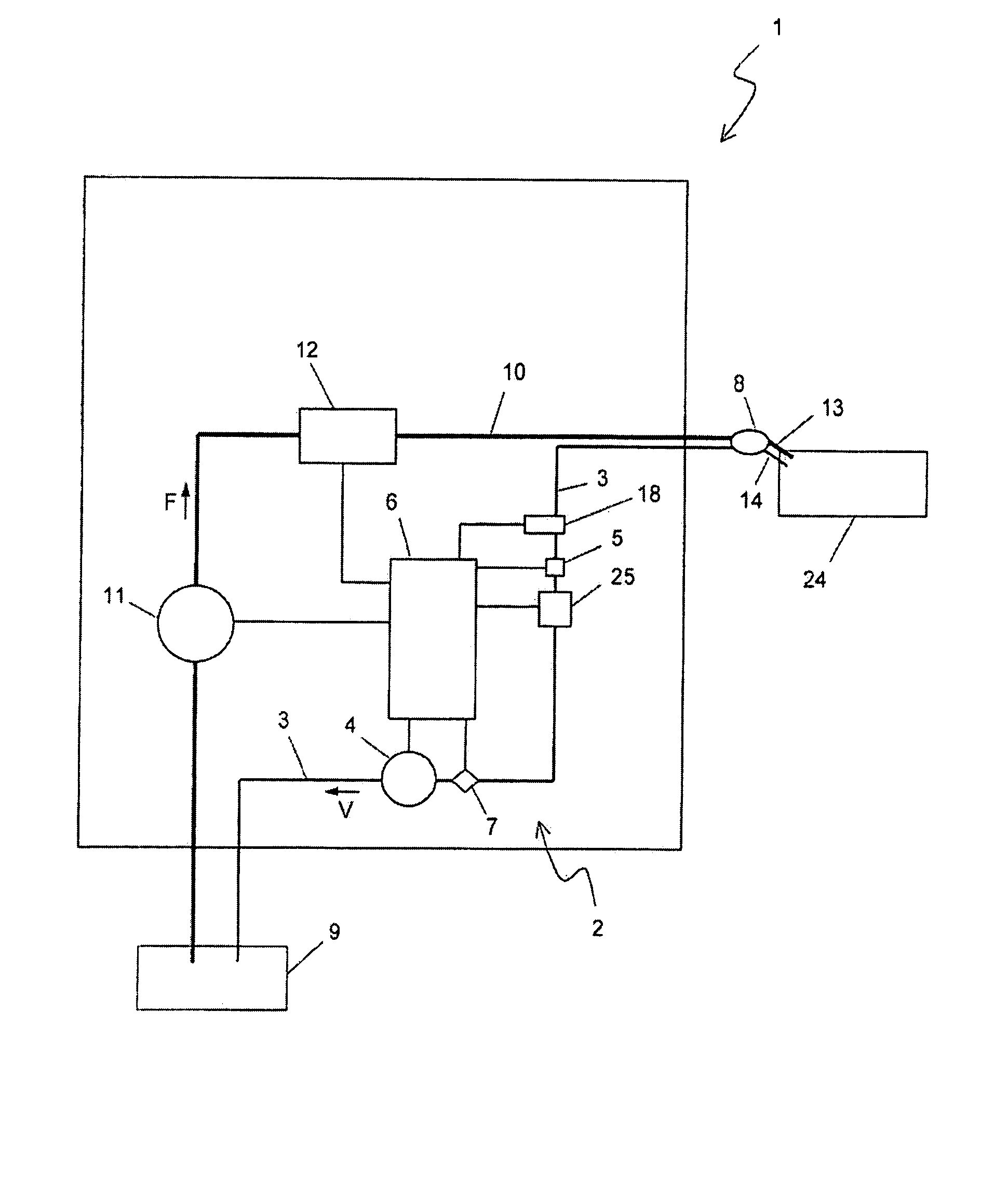
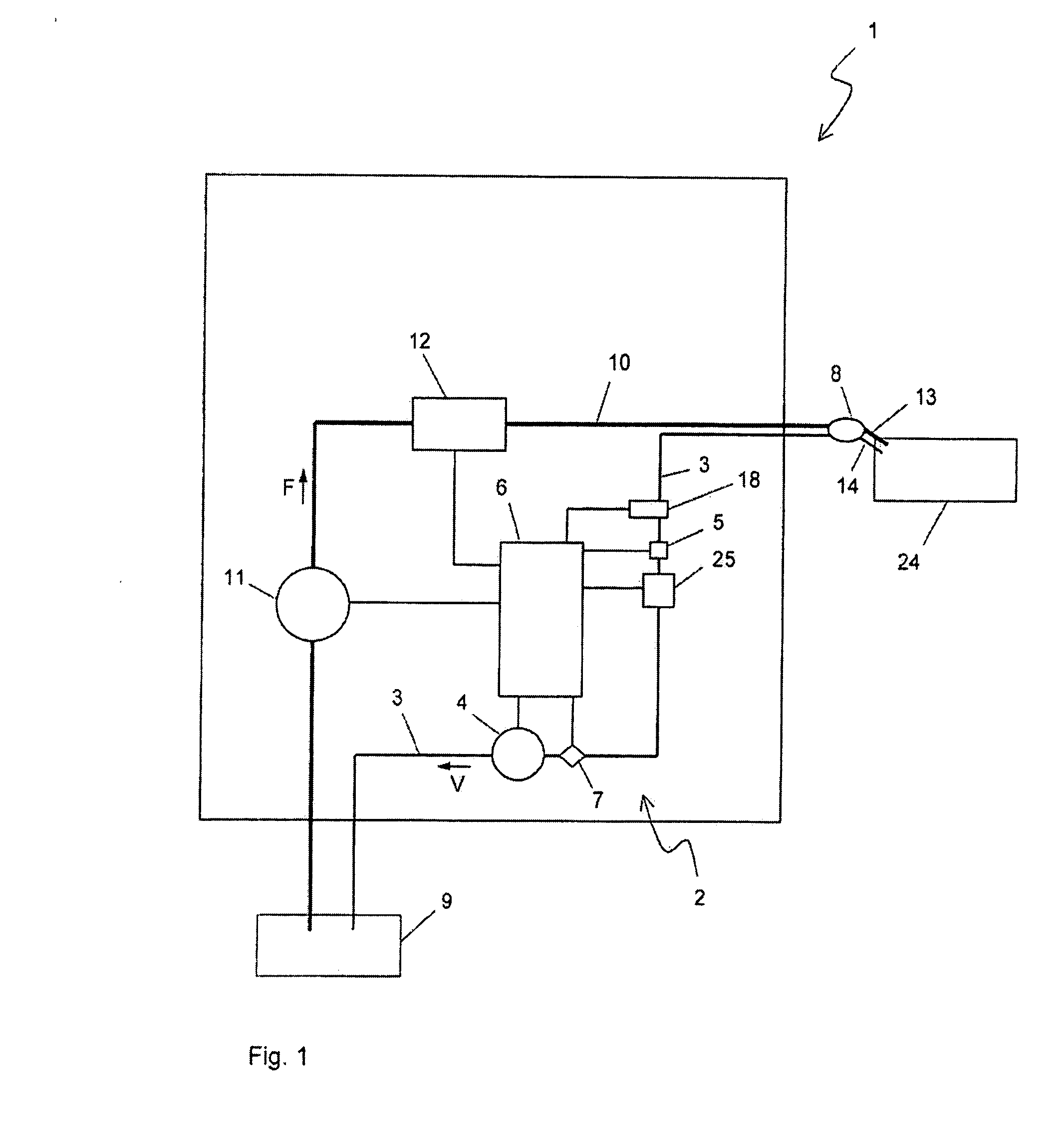
[0026] With reference to FIG. 1, a fuel dispensing unit 1 is illustrated having a fuel line 10 with a fuel pump 11 drawing fuel from a fuel storage tank 9 and producing a stream of fuel F to a fuel dispensing nozzle 8 fitted with a fuel outlet 13. The volume and rate of dispensed fuel is measured by a flow meter 12 arranged in the fuel line 10 and connected to control means 6.

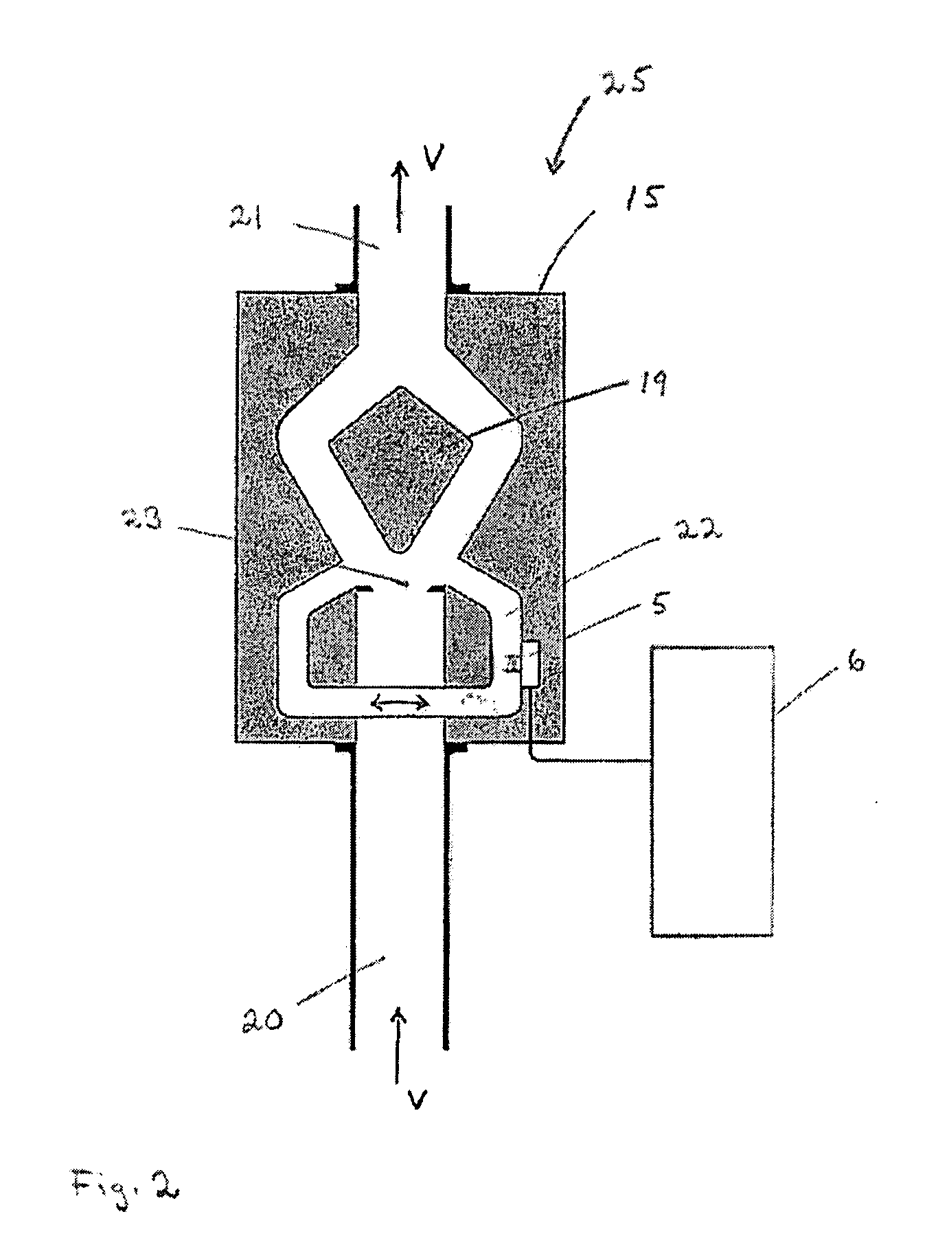
[0027] In the fuel dispensing unit 1 a vapor recovery system 2 is provided, in which a vapor line 3 in downstream order comprises a vapor inlet 14 arranged at the fuel dispensing nozzle 8, a temperature sensor 18 for detecting the temperature of a vapor stream V flowing in the vapor line 3, a heated element 5, a vapor flow meter 25, a regulation valve 7 regulating the vapor stream V, and a vapor pump 4 for generating (transporting) the stream of vapor V to the storage tank 9.

[0028] During operation, the fuel outlet 13 and the vapor inlet 14 normally are positioned at the fuel inlet (not shown) of a vehicle fu...


PUM

PropertyMeasurementUnit
Temperatureaaaaaaaaaa
Flow rateaaaaaaaaaa
Densityaaaaaaaaaa

Abstract

A vapor recovery system is configured to recover fuel vapor and comprises a vapor recovery line for transporting a stream of fuel vapor from a vehicle tank. A flow meter is arranged in the vapor recovery line for indicating the flow rate of the stream of fuel vapor, and a heated element is arranged in the vapor recovery line. Control means are configured to: detect a cooling exerted on the heated element by the stream of fuel vapor, determine a correction for the detected cooling by weighting said cooling with the flow rate, and decrease or stop the stream of fuel vapor, if the detected cooling is smaller than a predetermined level.

Description

REFERENCE TO PRIORITY APPLICATION [0001] The present application claims the benefit of European Patent Application No. 06121317.9 which was filed on Sep. 27, 2006. TECHNICAL FIELD [0002] The present invention relates to a vapor recovery system for recovering fuel vapor from a vehicle tank during dispensing of fuel into the vehicle tank. The vapor recovery system comprises a vapor recovery line for transporting a stream of fuel vapor, and control means for controlling the stream of fuel vapor. BACKGROUND ART [0003] When filling the fuel tank of a motor vehicle, it is a common measure to recover the vapor escaping the tank when filling it with liquid fuel. This measure is taken for both safety and environmental reasons. The vapor recovery is achieved, for instance, by arranging a vapor suction nozzle next to the fuel dispensing nozzle of a pistol grip for filling the tank with fuel. Vapor is then removed from the tank during filling, at a certain rate, which is often controlled by the...

Claims


Application Information

Patent Timeline
IPC IPC(8): B67D5/01B67D7/04B67D7/00
CPCG01F1/3227B67D7/048
Inventor LARSSON, BENGT I.HAKANSSON, MARIEKARLSSON, RICHARD
Owner WAYNE FUELING SYST
Why Eureka
Try Eureka