Mechanism for tensioning a compensation spring for a closing or sun protection installation

a compensation spring and installation technology, applied in the direction of curtain accessories, curtain suspension devices, building components, etc., can solve the problems of relatively complex devices and high cost, and achieve the effect of reliable and economical adjustment and convenient tension adjustmen

Active Publication Date: 2008-02-05
SIMU
View PDF7 Cites 16 Cited by
  • Summary
  • Abstract
  • Description
  • Claims
  • Application Information

AI Technical Summary

Benefits of technology

[0013]Means are provided for adjusting the intensity of the blocking effort. These means make it possible to reduce or to eliminate the effort exerted by the stop spring and thus to release one of the ends of the compensating spring in order to allow adjustment of its tension. These adjusting means advantageously comprise a ring mounted, with possibility of rotation, around an element of circular cross-section and provided with a projection adapted to be interposed between the curved ends of the stop spring.In addition, this ring may be provided to present catches or notches for interaction with a tool for controlling its angular position around the circular element. In this way, the tool makes it possible to exert on the ring an effort of rotation about the element of circular cross-section, this effort being transmitted by the projection to one or the other of the curved ends of the stop spring, this having the effect of expanding the latter by releasing the ring fast with the compensating spring which may in that case rotate in the desired direction. In a variant, the afore-mentioned adjusting means may comprise a shaft provided with a radial projection adapted to be interposed between the curved ends of the stop spring.
[0019]The invention finally relates to a closure / sun protection installation which comprises a mechanism as described previously. Such an installation is reliable and economical, while it offers the possibility of an easy adjustment of the tension of a compensating spring that it includes, without danger, on its site of use.

Problems solved by technology

It is therefore necessary for the operator to manipulate, in one hand, a tool for exerting a torque on the ring and, in the other hand, the locking screw, this involving a particular technical gesture which is not necessarily accessible to a person of little experience.
Such a device is relatively complex and expensive.

Method used


Image

  • Mechanism for tensioning a compensation spring for a closing or sun protection installation
  • Mechanism for tensioning a compensation spring for a closing or sun protection installation
  • Mechanism for tensioning a compensation spring for a closing or sun protection installation

Examples


first embodiment

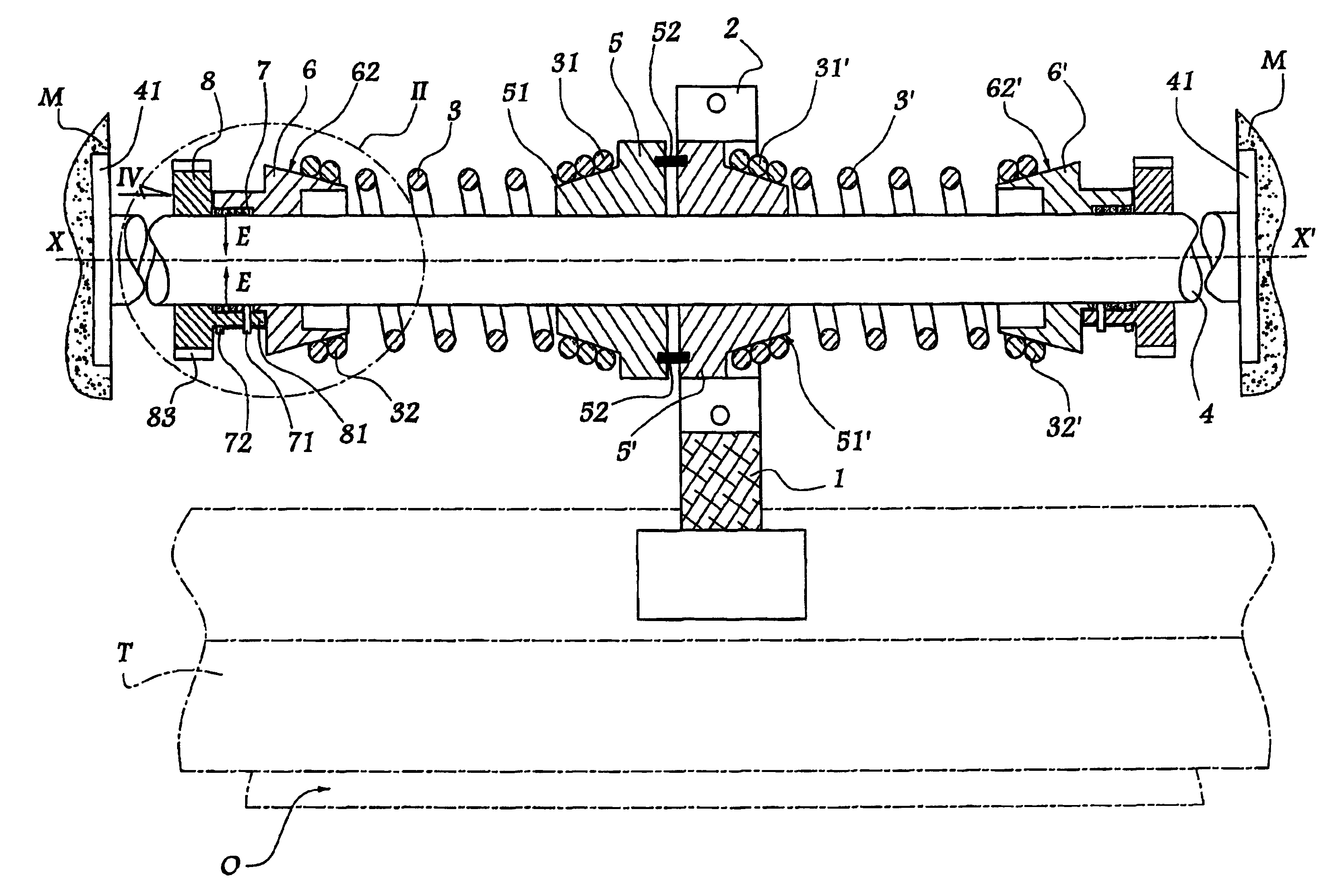
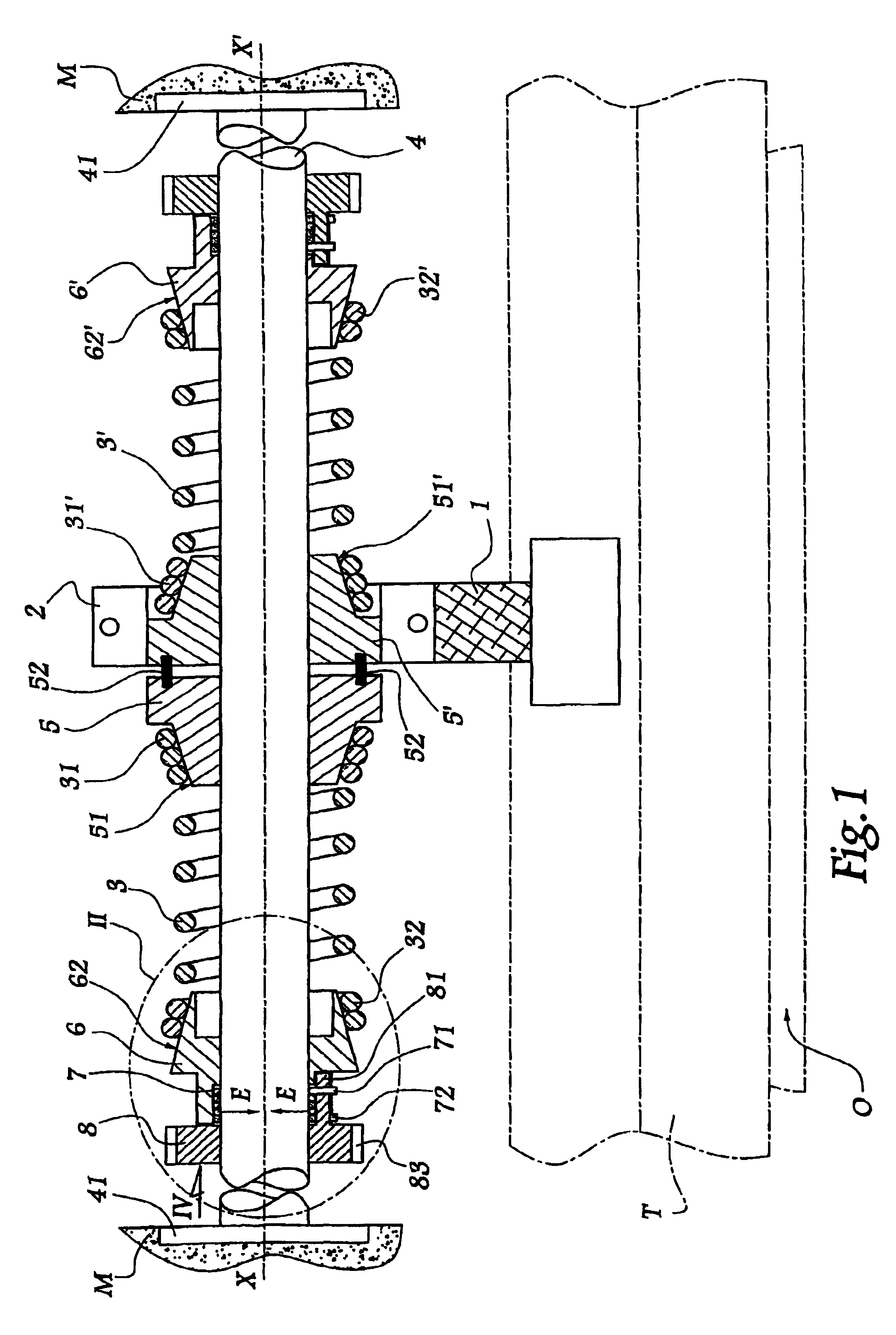
[0051]In the second form of embodiment of the invention shown in FIG. 5, elements similar to those of the first embodiment bear identical references increased by 100. In this installation, a fixed shaft 104 is immobilized with respect to the masonry M of a building thanks to brackets 141 and 141′. X-X′ denotes the longitudinal axis of the shaft 104. Two discs 102 and 102′ are mobile in rotation about the shaft 104 and axis X-X′ and allow the controlled winding of a screen body T intended to close an opening O.

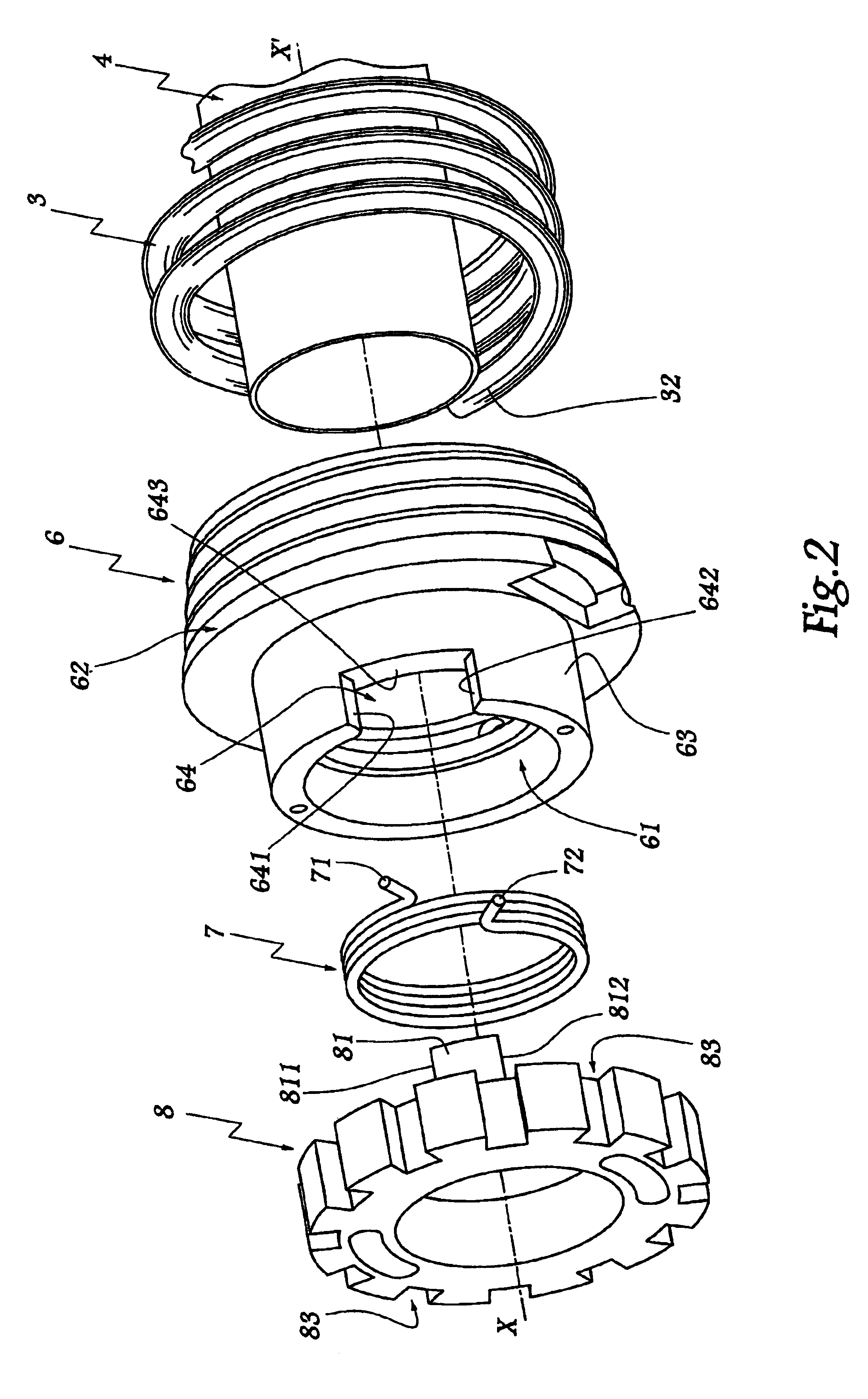
[0052]Two compensating springs 103 and 103′ each have a first end 131 or 131′ fast with a disc 102 or 102′ and a second end 132 or 132′ fast with a ring 106 or 106′ mounted, with possibility of rotation, on shaft 104. As previously, the ring 106 forms a sleeve 163 inside which is disposed a stop spring 107 of which the ends 171 and 172 are provided to interact with a projection 181 in one piece with a ring 108 mounted, with possibility of rotation, about the shaft 104. The cent...

fourth embodiment

[0069]As previously, a bracket 541 is fixed with respect to the masonry M of a building, this bracket supporting a casing 504 enclosing the same elements are the casing 304 of the An output shaft 544 of the casing 504 is fast with a disc 523 for driving the tube 545 in rotation. A ring 505 is fixed in rotation around the end of the casing 504 most remote from the bracket 541, while a second ring 506 is mounted about the end of this casing closest to the bracket with possibility of rotation.

[0070]A compensating spring 503 is tightened between the rings 505 and 506, while a third ring 508 is mounted, with possibility of rotation, about the casing 504, in the vicinity of the ring 506. The ring 508 is provided with a projection 581 adapted to be engaged in a notch 564 formed by the ring 506. A ring 504′ fast with the tube 545 is also mounted, with possibility of rotation and in the vicinity of the ring 506, around the casing 504, this ring 504′ forming a sleeve 547 which surrounds at l...


PUM


Abstract

The invention relates to a mechanism comprising at least one spring (3) for compensating the weight of a closing screen, said spring (3) being fixed, at one of its ends (32), to a ring (6) which is rotatably arranged around a shaft (4) having a circular cross-section. A stop spring (7) which is arranged around the shaft (4) ensures a one-way coupling between the ring (6) and the shaft (4), means (8) being provided for controlling the centripetal effort exerted on said shaft (4) by the stop spring (7).

Description

BACKGROUND OF THE INVENTION[0001]1. Field of the Invention[0002]The invention relates to a mechanism for manoeuvring a closing or sun protection installation. The invention also relates to a closing or sun protection installation incorporating such a mechanism.[0003]2. Brief Description of Related Art[0004]Closing installation is understood to mean doors, portals, blinds, shutters and equivalent equipment.[0005]In a closing or sun protection installation, a screen, which may be a supple shade body or a rigid or semi-rigid panel, is displaced opposite an opening in order to close the latter selectively. The weight of this screen exerts on the drive means a torque which is variable, particularly as a function of the position of this screen. It is known to use so-called “compensating” springs to compensate this torque at least partially.[0006]For an installation to function correctly, it is necessary that the effort of compensation exerted by the spring be adapted to the torque develop...

Claims


Application Information

Patent Timeline
Patent Type & Authority Patents(United States)
IPC IPC(8): E06B9/56E06B9/60
CPCE06B9/60
Inventor BOUSSON, BENJAMIN
Owner SIMU
Why Eureka
Try Eureka