Eureka AIR delivers breakthrough ideas for toughest innovation challenges, trusted by R&D personnel around the world.

Cable stripping device for power construction

A technology for electric power construction and cables, which is applied in the field of cable stripping devices, and can solve problems such as hand pain, wasted effort, and heat generation

Inactive Publication Date: 2020-10-30
宋允华
View PDF0 Cites 7 Cited by
  • Summary
  • Abstract
  • Description
  • Claims
  • Application Information

AI Technical Summary

Problems solved by technology

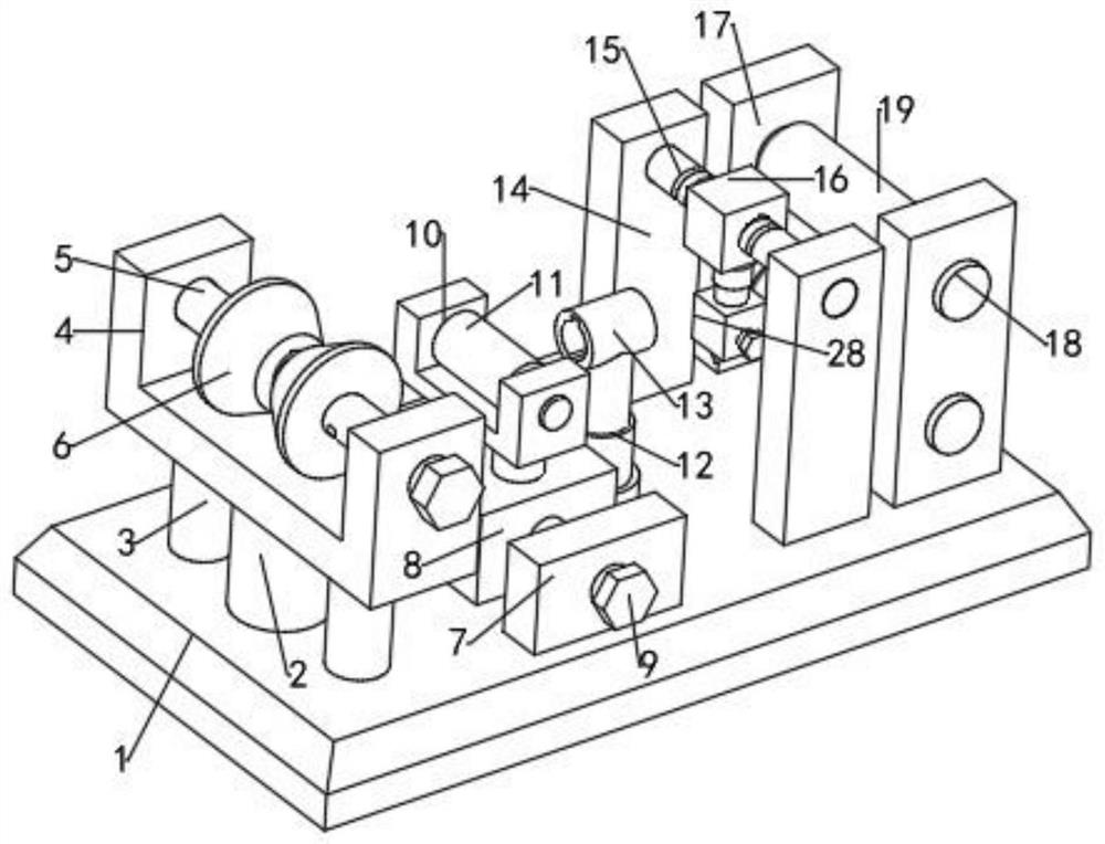
[0002] At present, electric power engineering refers to projects related to the production, transmission and distribution of electric energy. In a broad sense, it also includes projects that use electricity as power and energy in various fields; , it is often necessary to strip cables, cables and other lines. The existing stripping method is mainly to cut the outer skin with scissors, and then pull out the outer skin to expose the inner core of the line. This operation requires a large waste of time. strength, and heats up during pulling on the skin, causing pain in the hand

Method used


Image

  • Cable stripping device for power construction
  • Cable stripping device for power construction
  • Cable stripping device for power construction

Examples


Embodiment 1

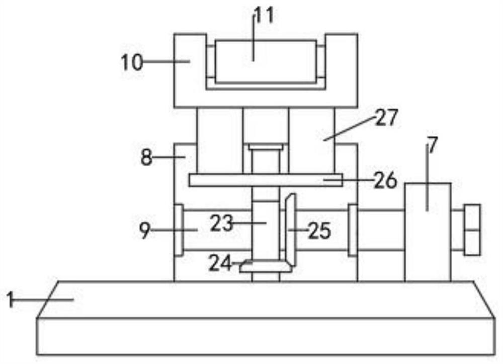
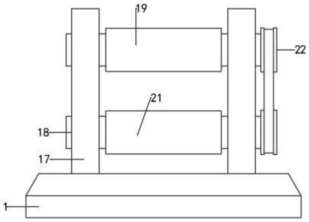
[0022] see Figure 1-6 , a cable stripping device for electric power construction, comprising a base 1, a mounting seat 4 is arranged on one side of the upper end surface of the base 1, a clamping mechanism is arranged on the mounting seat 4, and one side of the clamping mechanism is arranged in sequence There is a cutting mechanism and a winding mechanism; the clamping mechanism includes a clamping disc 6, a vertical frame 2 is fixedly connected between the lower end of the mounting seat 4 and the base 1, and vertical frames are arranged on both sides of the frame 2. The supporting rod 3 is used to enhance the connection strength between the mounting base 4 and the base 1; the cross section of the mounting base 4 is concave, and the mounting base 4 is equipped with a horizontal adjusting screw 5, and one end of the adjusting screw 5 extends to the installation The outer side of the seat 4; the adjusting screw 5 is equipped with two oppositely arranged clamping discs 6, the cl...

Embodiment 2

[0031] In order to facilitate the installation and fixation of the cable stripping device for electric power construction in actual use, this embodiment is improved on the basis of embodiment 1. The improvement is: the four corners of the base 1 are provided with through threads holes, so that in actual use, the cable stripping device for electric power construction is clamped and fixed with bolts, which is convenient for operation.


PUM


Abstract

The invention discloses a cable stripping device for power construction, the device comprises a base, a mounting seat is arranged on one side of the upper end surface of the base, a clamping mechanismis arranged on the mounting seat, and a cutting mechanism and a winding mechanism are sequentially arranged on one side of the clamping mechanism. According to the cable stripping device for electricpower construction, the distance between clamping discs can be conveniently changed through an adjusting screw rod, and the clamping of cables of different sizes is facilitated; the clamping discs comprise inner rings and outer rings which are rotationally connected with each other, so that the continuous transmission during cable stripping is facilitated; a sliding screw rod is matched with a lifting hydraulic cylinder, so that the position of a cutter is conveniently adjusted; an upper winding roller and a lower winding roller are arranged, so that a surface layer and an inner line layer are separately wound; a tensioning roller can be adjusted to ascend and descend by rotating a driving rod, so that the tensioning degree of cable clamping is convenient to adjust; besides, a guide ringwith the adjustable height is arranged so that the cooperation with the tensioning roller is facilitated, and thus the continuous stripping of the cable is enabled to be more stable.

Description

technical field [0001] The invention relates to the field of electric power technology, in particular to a cable stripping device for electric power construction. Background technique [0002] At present, electric power engineering refers to projects related to the production, transmission and distribution of electric energy. In a broad sense, it also includes projects that use electricity as power and energy in various fields; , it is often necessary to strip cables, cables and other lines. The existing stripping method is mainly to cut the outer skin with scissors, and then pull out the outer skin to expose the inner core of the line. This operation requires a large waste of time. Strength, and heat in the process of pulling the skin, causing pain in the hand. Contents of the invention [0003] The object of the present invention is to provide a cable stripping device for electric power construction, so as to solve the problems raised in the above-mentioned background t...

Claims


Application Information

Patent Timeline
Patent Type & Authority Applications(China)
IPC IPC(8): H02G1/12
CPCH02G1/1248H02G1/1278
Inventor 宋允华
Owner 宋允华
Why Eureka
Eureka Blog
Learn More