
Block for embankment

a technology for embankments and blocks, applied in piers, groynes, artificial islands, etc., can solve the problems of increasing fabrication costs, reducing work efficiency, and unable to move and engage blocks, so as to achieve easy transfer and engagement work, simple and light structure, and easy fabrication

Inactive Publication Date: 2008-02-05
LEE KANG SAN
View PDF22 Cites 9 Cited by
  • Summary
  • Abstract
  • Description
  • Claims
  • Application Information

AI Technical Summary

Benefits of technology

"The present invention provides an embankment block that overcomes the problems of conventional art. The block has a simple and light structure, making it easier to fabricate, transfer, and engage with other blocks. The block includes a base frame and multiple connection members that extend from the base frame. The connection members are slanted and wider at the outer edge of the base frame. The front portion of the connection member has a reinforcing rib and a connection hole to connect with other blocks. The block also has an engaging protrusion and an engaging hole to connect with other blocks. Overall, the invention provides a more efficient and reliable embankment system."

Problems solved by technology

However, the conventional embankment blocks have complicated structure and heavy, so that it is impossible to fabricate, move and engage the blocks.
Therefore, it has problems that can cause the increase of the fabrication cost, and the decrease of work efficiency.

Method used


Image

  • Block for embankment
  • Block for embankment
  • Block for embankment

Examples


Embodiment Construction

[0026]The preferred embodiments of the present invention will be described with reference to the accompanying drawings.

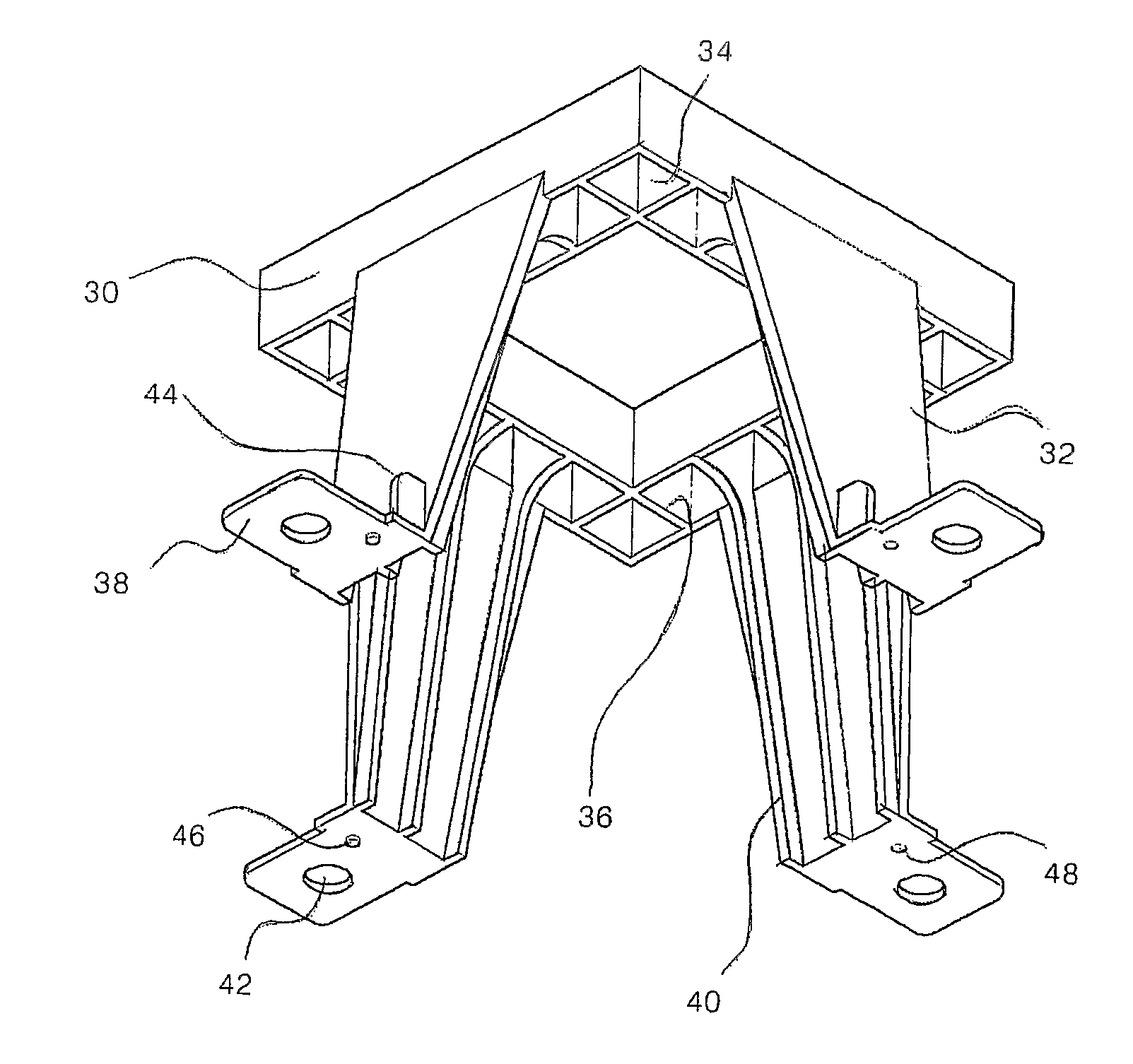
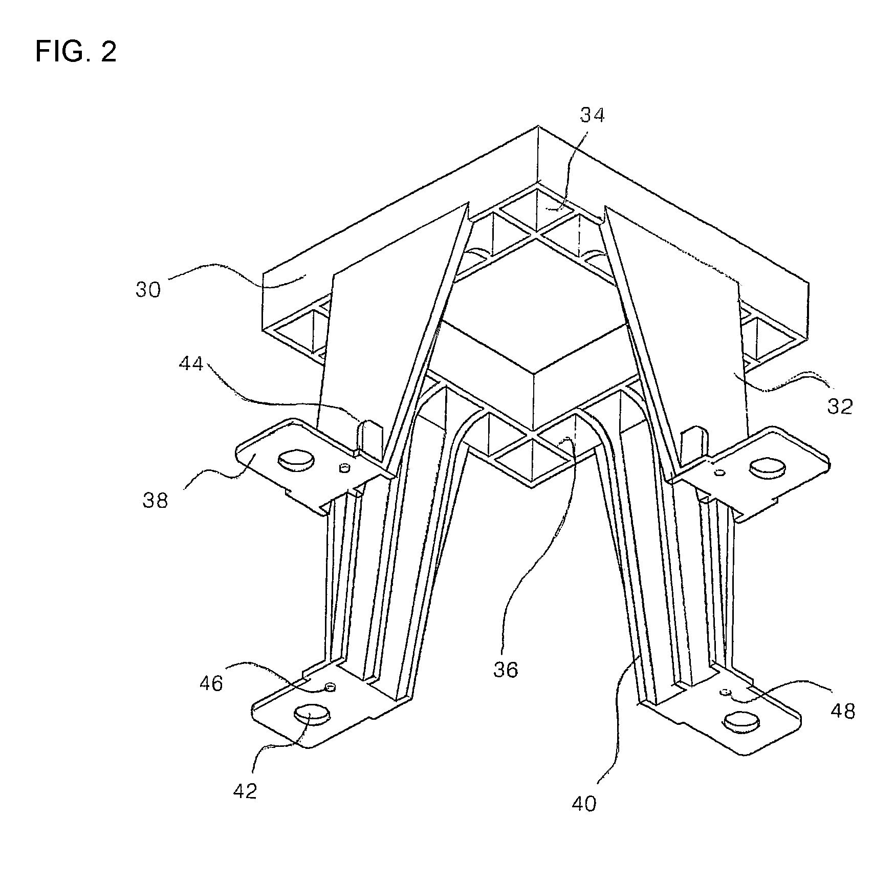
[0027]As shown in FIG. 2, the embankment block according to the present invention includes a base frame 30 having a center portion with a through hole, and a plurality of connection members 32 downwardly extended from a rim of the base frame 30.

[0028]The base frame 30 is formed of a rectangular frame shape having a certain width. The base frame 30 includes a through hole 34 formed at its center. A plurality of partition plates 36 partition the through hole 34 by a certain width.

[0029]The connection members 32 are downwardly extended from an outer surface of a rim of the base frame 30, and a connection part 38 is provided at an extended end portion wherein the connection part 38 is outwardly bent.

[0030]The connection members 32 are widened in an outer direction of the rim and are slanted at a certain slope. A plurality of reinforcing ribs 40 are formed in an inner su...


PUM


Abstract

The present invention relates to an embankment block. There are provided a base frame 30 having a center with a through hole, and a plurality of connection members 32 that are downwardly extended from an outer surface of a rim of the base frame 30 wherein a front end of the same has an outwardly bent connection part 38. A plurality of through holes 34 are formed in a rim of the base frame 30 wherein said through holes 34 vertically pass through by the partition plate 36. The connection member 32 is widened in an outer direction of the rim of the base frame 30 and is slanted at a certain slope.

Description

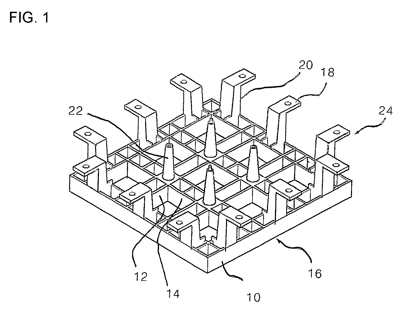
TECHNICAL FIELD[0001]The present invention relates to a block for embankment, and in particular to an embankment block that has a simple structure and is easily fabricated, and a handling and construction of the same are easy, and embankment blocks may be connected in various methods, so that the embankment blocks are well adapted to an embankment and slanted surface.BACKGROUND ART[0002]Generally, an embankment block is used for preventing a destruction of a bank or slanted surface of river and helps plants grow well.[0003]In the existing Korean patent invented by the same inventor as the present invention concerning the embankment block, as shown in FIG. 1, presents a block for embankment 24 that has a base frame 16 that has a rim part 10, and a horizontal part 12 and a vertical part 14 that cross in the rim part 10 each other, a connection member 20 extended from a lower surface of the rim part 10 and having a connection part 18 in a front end of the same, and a support protrusion...

Claims


Application Information

Patent Timeline
Patent Type & Authority Patents(United States)
IPC IPC(8): E02B3/12E02B3/14E02D17/20E02D29/02
CPCE02B3/14E02D17/205E02D29/025E02D29/0266E02D29/02E02D17/20
Inventor LEE, KANG-SAN
Owner LEE KANG SAN
Learn More