Injection compression molding method and injection compression machine of lens

a technology of injection compression molding and injection compression molding, which is applied in the direction of manufacturing tools, instruments, food shaping, etc., can solve the problems of high production cost, easy deformation of molding articles, and failure of so-called “separation” parts, so as to reduce sink mark and strain, and shorten the molding cycle

Active Publication Date: 2008-02-05
HOYA CORP
View PDF19 Cites 9 Cited by
  • Summary
  • Abstract
  • Description
  • Claims
  • Application Information

AI Technical Summary

Benefits of technology

[0015]An object of the present invention is to provide an injection compression molding method of a lens and an injection compression molding machine capable of reducing sink mark and strain and shortening molding cycle.

Problems solved by technology

Accordingly, deformation is likely to be caused on the molding article during the die-releasing step if the cooling time is not sufficient.
Further, there can be partial parting (peeling) between the dies and the molding article according the manner for opening the dies during the die-releasing step, which causes parting failure of so-called “separation”.
Accordingly, a plurality of types of molding dies have to be prepared and much production cost is necessary, and additional work is required for exchanging the molding die, thereby deteriorating production efficiency.

Method used


Image

  • Injection compression molding method and injection compression machine of lens
  • Injection compression molding method and injection compression machine of lens
  • Injection compression molding method and injection compression machine of lens

Examples


Embodiment Construction

)

[0072]An embodiment of the present invention will be described in detail below with reference to attached drawings.

[Machine Arrangement]

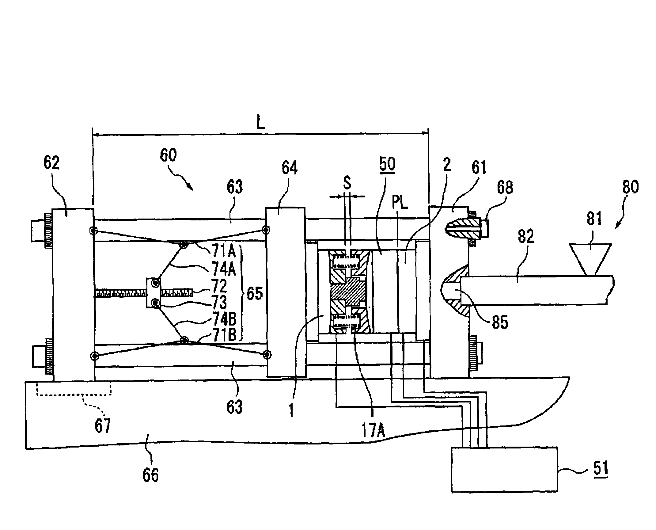
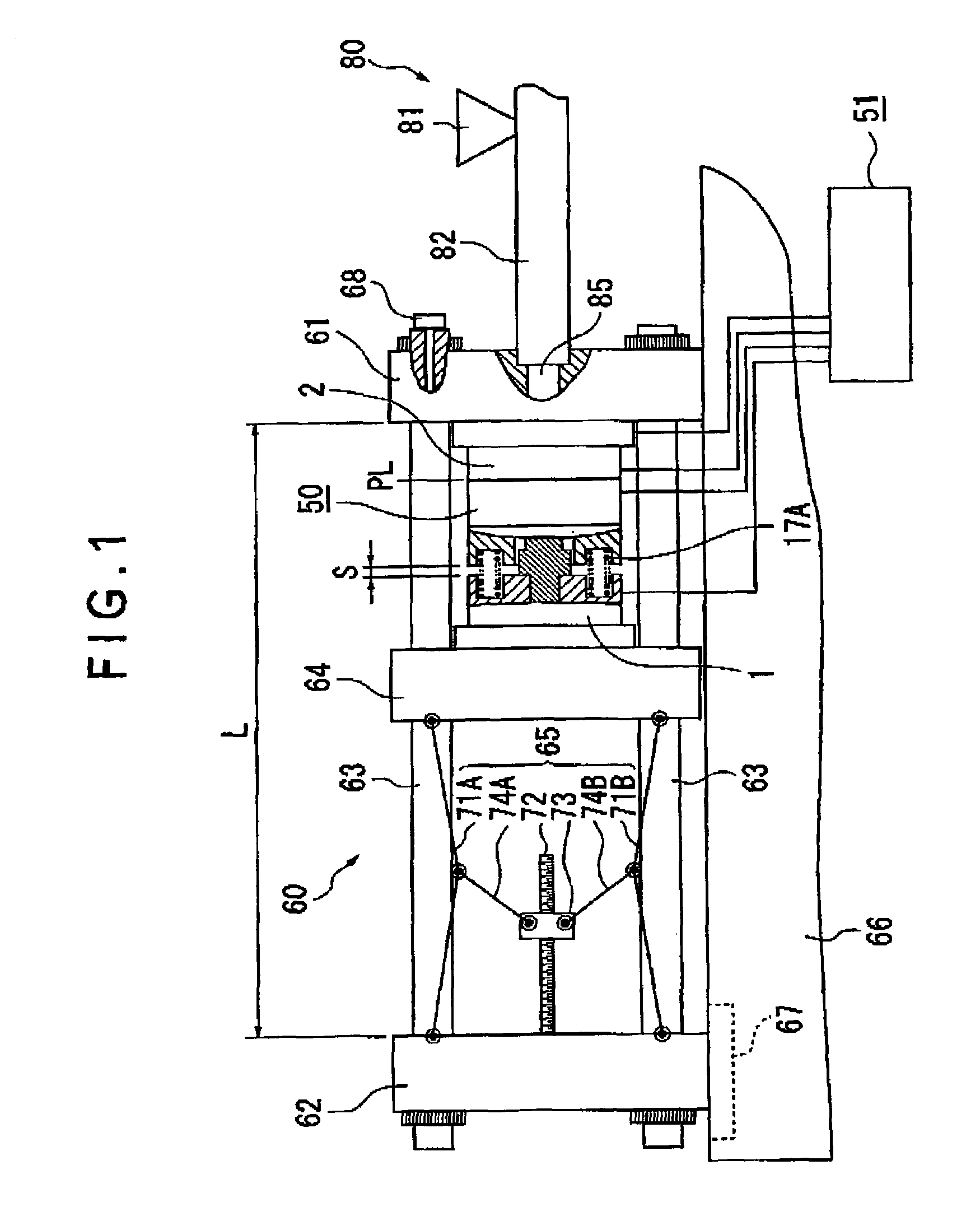
[0073]In the present embodiment, the injection compression molding method of the present invention is applied to an injection compression molding machine of a spectacles lens (meniscus-shaped spectacles lens: single-vision, multifocal, or progressive-power) of which entire arrangement is shown in FIG. 1. The material of the spectacles lens molded therein is thermoplastic resin such as PMMA (polymethyl methacrylate) and PC (polycarbonate).

[0074]The injection compression molding machine of the present embodiment has a clamping device 60 having a molding die 50, an injection device 80 as an injection means for injecting plasticized and measured material resin to fill the molding die 50 and a die temperature adjuster 51 for controlling the temperature of the molding die at a predetermined temperature.

[0075]The clamping device 60 has a fixed die plate 6...


PUM

PropertyMeasurementUnit
diameteraaaaaaaaaa
central thicknessaaaaaaaaaa
thicknessaaaaaaaaaa

Abstract

An injection compression molding method of a lens is provided, where a toggle link mechanism (65) is actuated to close a molding die (50) and a movable die plate (64) is moved to a position establishing a cavity thickness of greater than a thickness of an article to be molded while the die is closed. After injecting a molten resin into the cavity, the molten resin is sealed in the cavity and the toggle link mechanism (65) is actuated to advance the movable die plate (64) toward a fixed die plate (61), the relative position of a rear die plate (62) and the movable die plate (64) is made constant at a position where extension of a tie bar (63) becomes a predetermined value, and the molten resin is cooled for a predetermined time after completion of pressurizing the resin.

Description

BACKGROUND OF THE INVENTION[0001]1. Field of the Invention[0002]The present invention relates to injection compression molding method and machine of a lens for injecting and compressing thermoplastic resin to mold a lens. More specifically, it relates to an injection compression molding method and an injection compression molding machine of a lens capable of reducing sink mark and strain, restraining strain of molding article, and easily changing the thickness of the molding article, which is suitable for molding a spectacles-lens.[0003]2. Description of Related Art[0004]Conventionally, an injection compression molding method is known as a method for molding spectacles lenses using thermoplastic resin.[0005]In the injection compression molding method, in order to compensate shrinkage of molten resin to obtain uniform and high shape accuracy, molding die is clamped while retaining compression margin inside the spectacles-lens molding cavity, the molten resin is injected and filled in...

Claims


Application Information

Patent Timeline
Patent Type & Authority Patents(United States)
IPC IPC(8): B29D11/00B29C45/56
CPCB29C45/561B29D11/00413B29D11/00423B29C45/7653Y10S425/808B29C2945/76013B29C2945/76107B29C2945/76234B29C2945/76331B29C2945/76354B29C2945/76391B29C2945/76481B29C2945/76505B29C2945/76585B29C2945/76591B29C2945/76702B29C2945/76765B29C2945/76769B29C2945/76832B29C2945/76869B29L2011/0016
Inventor NISHIMOTO, TATSUOSAITO, KIYOHIROTANAGAWA, KENJIUCHIDA, TETSUYA
Owner HOYA CORP
Why Eureka
Try Eureka