Flexible corrugated hose assembly and connecting process

a corrugated hose and flexible technology, applied in the direction of hose connection, manufacturing tools, mechanical equipment, etc., can solve the problems of reducing and affecting the service life of the corrugated hose. , to achieve the effect of reducing or preventing the deformation of the corrugated hos

Inactive Publication Date: 2008-02-12
EATON FLUID POWER GMBH
View PDF17 Cites 11 Cited by
  • Summary
  • Abstract
  • Description
  • Claims
  • Application Information

AI Technical Summary

Benefits of technology

[0017]The second section of the holder can be in an interlocking connection with the sheathing of the flexible corrugated hose. For this purpose, the second section can be compressed radially inward, for example by pressing in a narrow or wider ring-shaped area. If the pressing is performed in a narrow ring-shaped area, the latter is preferably arranged between two ribs of the corrugated pipe in order to reduce or prevent a deformation of the corrugated pipe.

Problems solved by technology

However, because of this, the lengths of the conductors are already limited to production-generated “fixed lengths”.
Therefore the connection of flexible corrugated hoses which have no connecting nipples poses a particular problem.
Neither pressure loads nor mechanical stresses, such as are to be expected during the operation of respective installations or units, should or may lead to leakiness, or any other damage of the connection.

Method used


Image

  • Flexible corrugated hose assembly and connecting process
  • Flexible corrugated hose assembly and connecting process
  • Flexible corrugated hose assembly and connecting process

Examples


Embodiment Construction

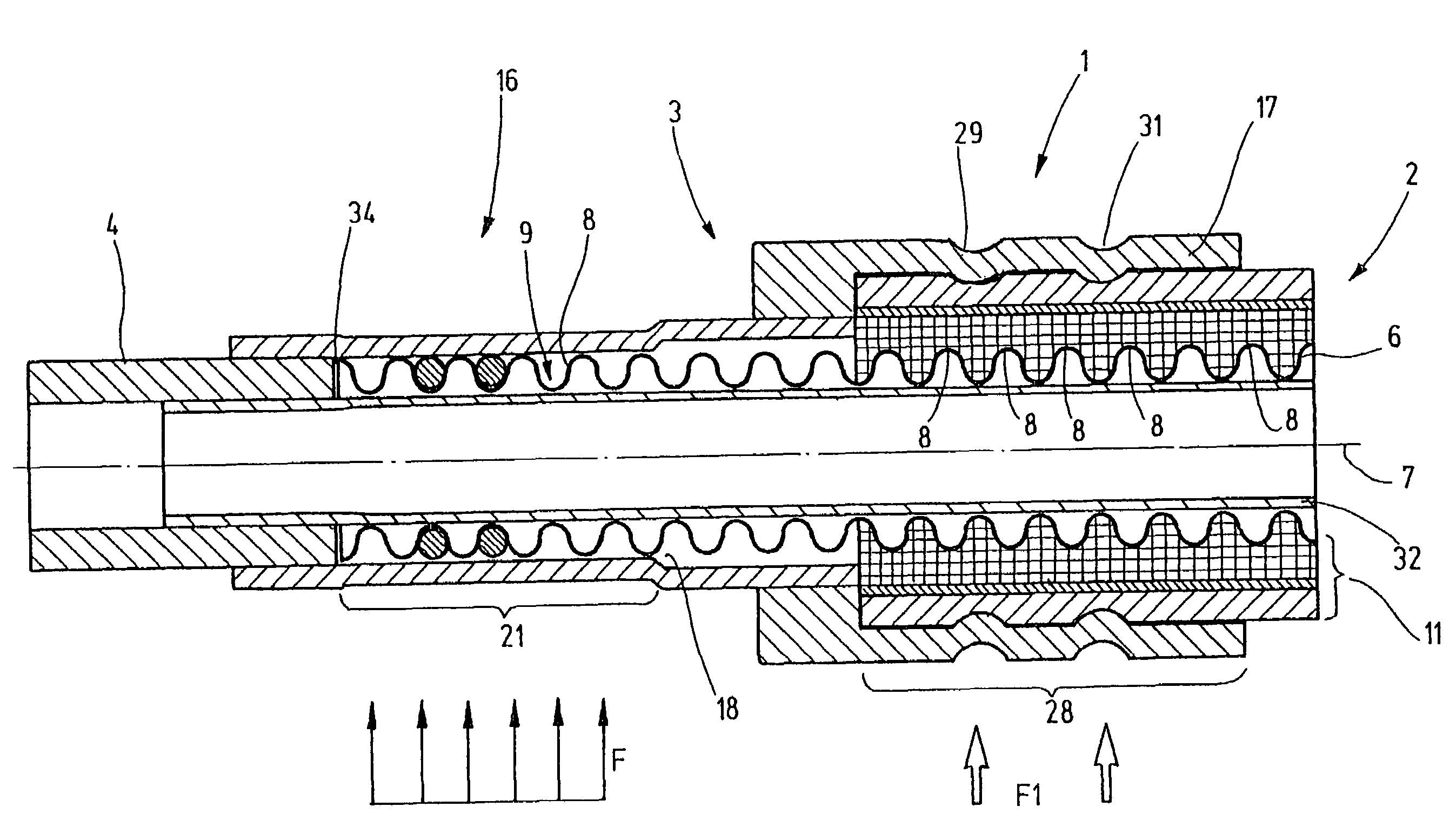
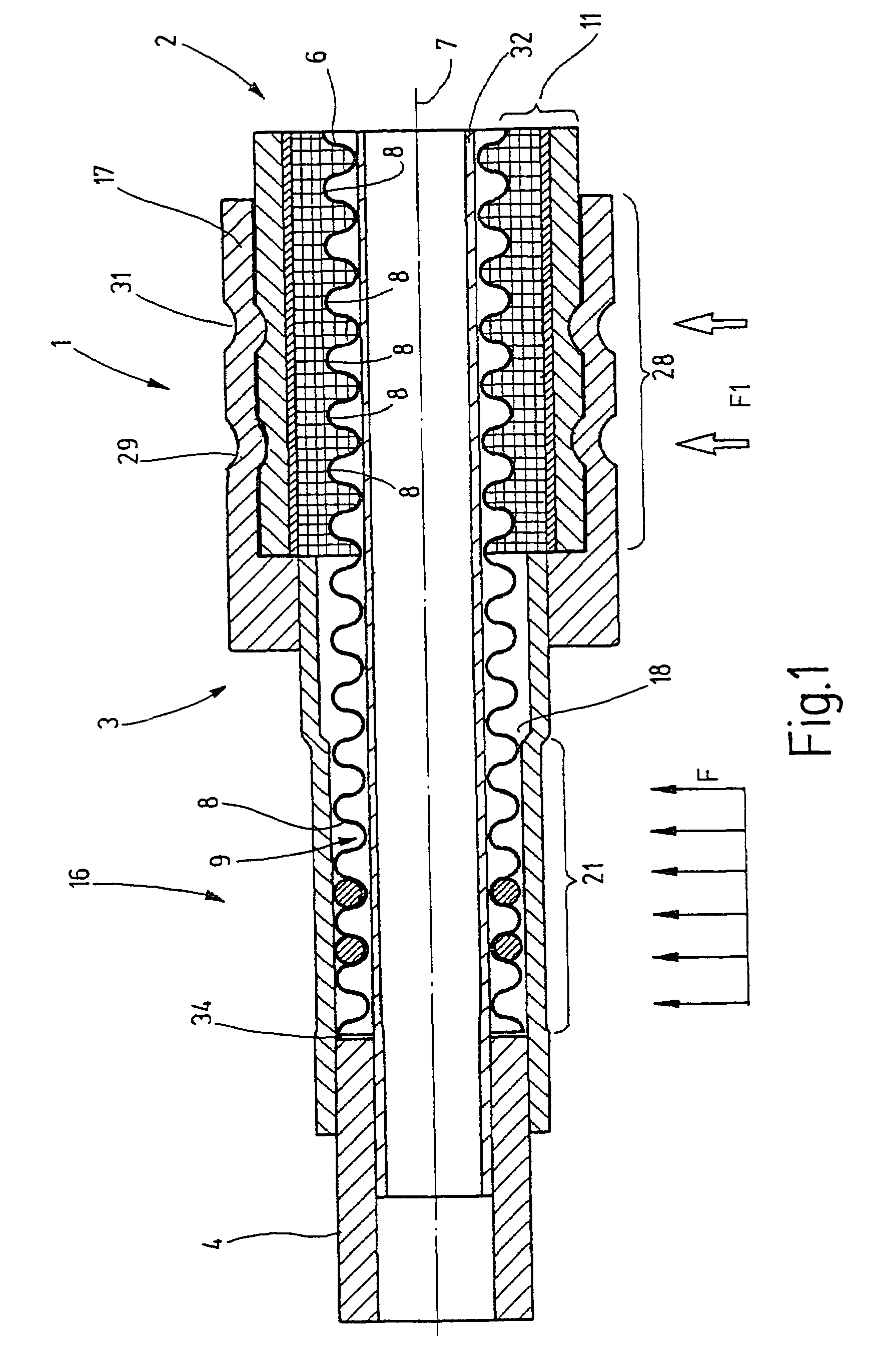
[0029]A flexible corrugated hose assembly 1 is partially shown in FIG. 1. The flexible corrugated hose assembly 1 contains a flexible corrugated hose 2, which constitutes a flexible fluid conductor. The flexible corrugated hose 2 is connected via a holder 3 to a pipe element 4 or other conducting means. Another connecting piece, which constitutes a continuing conductor, or is an element of a connected unit, such as a unit which is a part of a refrigerating installation, can also be provided in place of the pipe element 4. Flexible corrugated hose assemblies of the type illustrated in FIG. 1 are suitable for use in refrigerating installations for motor vehicles for the flexible and vibration-resistant fluid connection between individual units or components of the refrigerating installation. In particular, the flexible corrugated hose assembly 1 is suitable for connecting chambers containing fluids which are under a high interior pressure of up to several hundred bar.

[0030]The flexibl...


PUM


Abstract

For connecting flexible corrugated hoses, which are not provided with fittings, for transporting preferably gaseous media in connection with high-pressure applications, a holder 3 is provided, which receives an exposed end of the corrugated pipe 6 of the flexible corrugated hose 2 and is pressed together with it to form a metallic seal. The metallic seal is achieved by the surface pressure between the interior wall 18 of an element 16 of the holder and the ribs 8 of the corrugated pipe 6. Elastomeric seals 24, 25, as well as a soldering joint 34, if desired, can be provided as aids. However, in connection with a preferred embodiment the required sealing is already achieved by the strong pressure against each other of the metallic exterior of the corrugated pipe 6 and the metallic interior of the element 16. A further element 17 of the holder 3 fixes a section 28 of the sheathing 11 of the flexible corrugated hose 2 in the axial direction, as well as in respect to tilting movements, so that pivot movements of the flexible corrugated hose 2 do not lead to a relative movement between the corrugated pipe 6 and the holder 3, in particular the element 16. Thus, the sealed area remains unaffected, even in case of mechanical tensile or bending stresses of the flexible corrugated hose assembly 1.

Description

BACKGROUND OF THE INVENTION[0001]The invention relates to a flexible corrugated hose assembly and to a method for connecting a flexible corrugated hose for producing such a flexible corrugated hose assembly.DESCRIPTION OF THE RELATED ART[0002]So-called flexible corrugated hoses are used as fluid conductors, in particular for the flexible connection of fluid-conducting units. They have an inner corrugated pipe, which defines a fluid channel. The corrugated pipe, most often made of metal, is enclosed in sheathing essentially consisting of plastic, elastomer materials, as well as further components. Often the sheathing is a multi-layered construction. It consists for example of a hose core, which is directly connected with the corrugated pipe. The hose core frequently supports a so-called pressure backing, which is wound from a tension-resistant material in order to assure the pressure resistance of the flexible corrugated hose. In most cases a hose cover is also applied to the pressur...

Claims


Application Information

Patent Timeline
Patent Type & Authority Patents(United States)
IPC IPC(8): F16L33/00F16L25/00F16L33/20F16L33/207
CPCF16L25/0036F16L33/2073Y10S285/903Y10T29/49913
Inventor SCHNEIDER, AXELHILGERT, ANDREAS
Owner EATON FLUID POWER GMBH
Why Eureka
Try Eureka