Induction generator power supply

a technology of induction generator and power supply, which is applied in the direction of emergency power supply arrangement, electric generator control, single ac network with different frequencies, etc., can solve the problems of limited driving range and the time required to recharge batteries, limited the use of induction generators, and electric vehicles have suffered, so as to achieve low distortion sine wave output and less cost

Active Publication Date: 2008-02-12
COLLEY BRUCE H
View PDF17 Cites 14 Cited by
  • Summary
  • Abstract
  • Description
  • Claims
  • Application Information

AI Technical Summary

Benefits of technology

[0029]The present invention helps to make hybrid electric technology a much more practical means for realizing benefits of increased fuel economy and decreased emissions levels. The present invention is based in part on the recognition that a solution for overcoming the disadvantage of the induction generator's inability to power reactive loads is to rectify the output. If three phase power is rectified, the result is a low ripple, almost pure DC waveform. Pure DC power is resistive and not reactive, since there is no time variation in the voltage waveform that can cause the voltage and current to be out of phase. For AC loads (resistive or reactive) a DC to AC inverter can then be added. An induction generator is therefore well suited for such applications since its above-mentioned advantages can then be realized, while its major disadvantage is overcome. Conversion to DC power also makes it possible to take advantage of energy storage, such as in a battery bank. Utilization of the induction generator in this manner then leads to two broad areas of application.
[0032]For either application, using such an approach now allows the engine (or other prime mover) and the generator to be sized according to the average power requirements instead of the peak power requirements. (Examples of other prime movers include an external combustion engine, or a wind or water turbine.) The battery bank must then be sized so as to be capable of powering the higher than average loads for expected periods of duration at the expected power levels. (Alternatively, other means of energy storage such as a capacitor bank, inductor, flywheel, elevated water storage, or compressed air could be utilized, but a battery bank appears to be the most practical for most applications.) For independent AC power generation, the use of modern sine wave inverters results in a very low distortion sine wave output, and such devices can power single phase or three phase resistive loads, or reactive loads with power factors of 0 to 1.0. Thus, the limitation of the induction generator in powering only resistive loads has been overcome, and the result is a generator that is available in a wide power range that is more rugged and less costly than was previously possible.
[0033]Compared to the present invention, conventional generators that have traditionally been used in hybrid electric systems (1. synchronous, automotive type (alternators), or commercial / industrial, 2. shunt wound DC, or 3. permanent magnet) have one or more of the following disadvantages:

Problems solved by technology

Electric vehicles have suffered from disadvantages of limited driving range and the time required to recharge batteries.
Practical limitations, however, have restricted the use of such induction generators.
However, an induction generator can only be used to power resistive loads.
The resulting instability of the output voltage renders the generator unsuitable for normal operation, since a fairly constant voltage is normally required.
Various compensating schemes to offset the effect of reactive loads on the magnetizing current can become expensive and complex.
Since reactive AC power loads are extremely common, the induction generator has been of limited usefulness for independent AC power generation.

Method used


Image

  • Induction generator power supply
  • Induction generator power supply
  • Induction generator power supply

Examples


Embodiment Construction

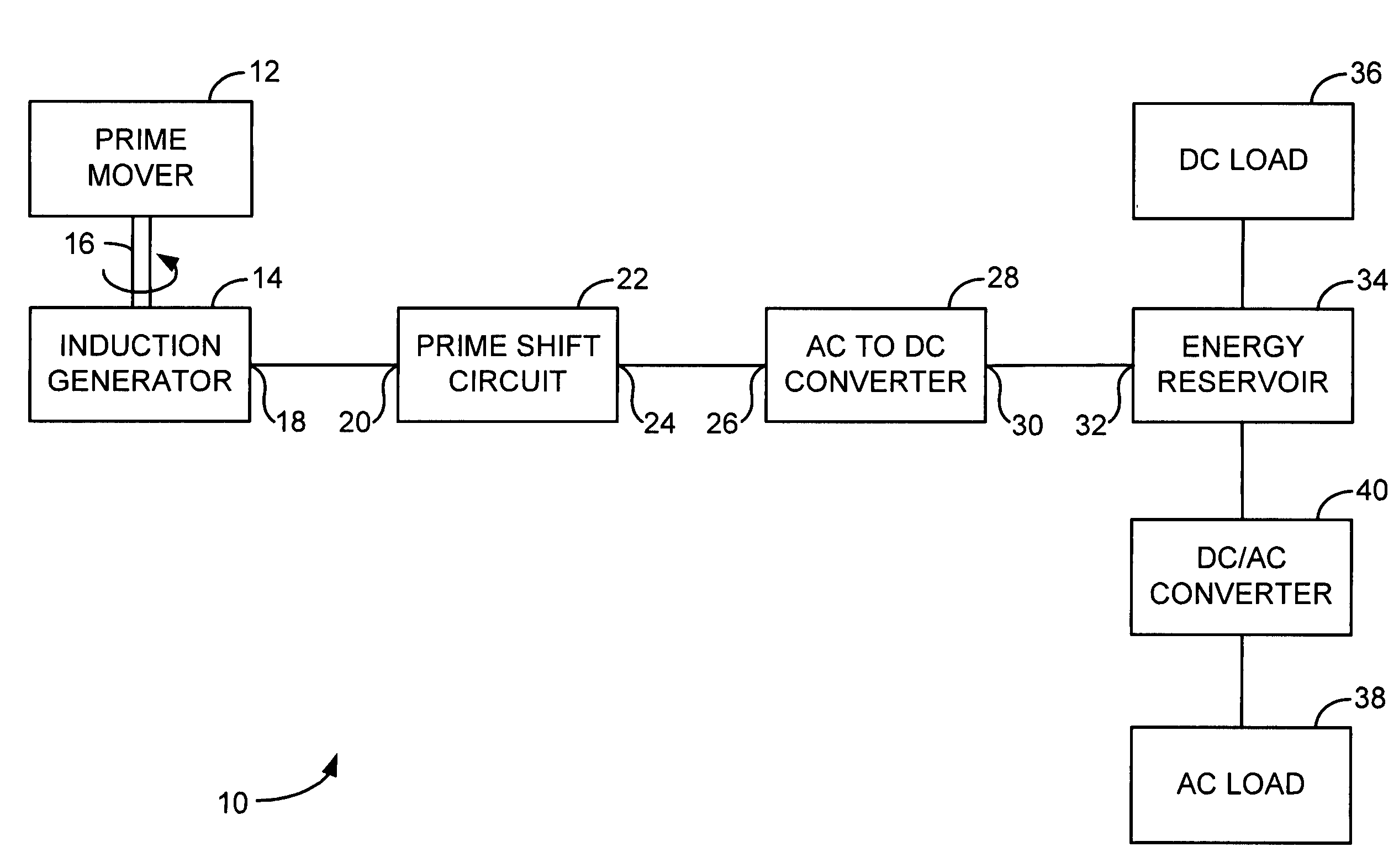
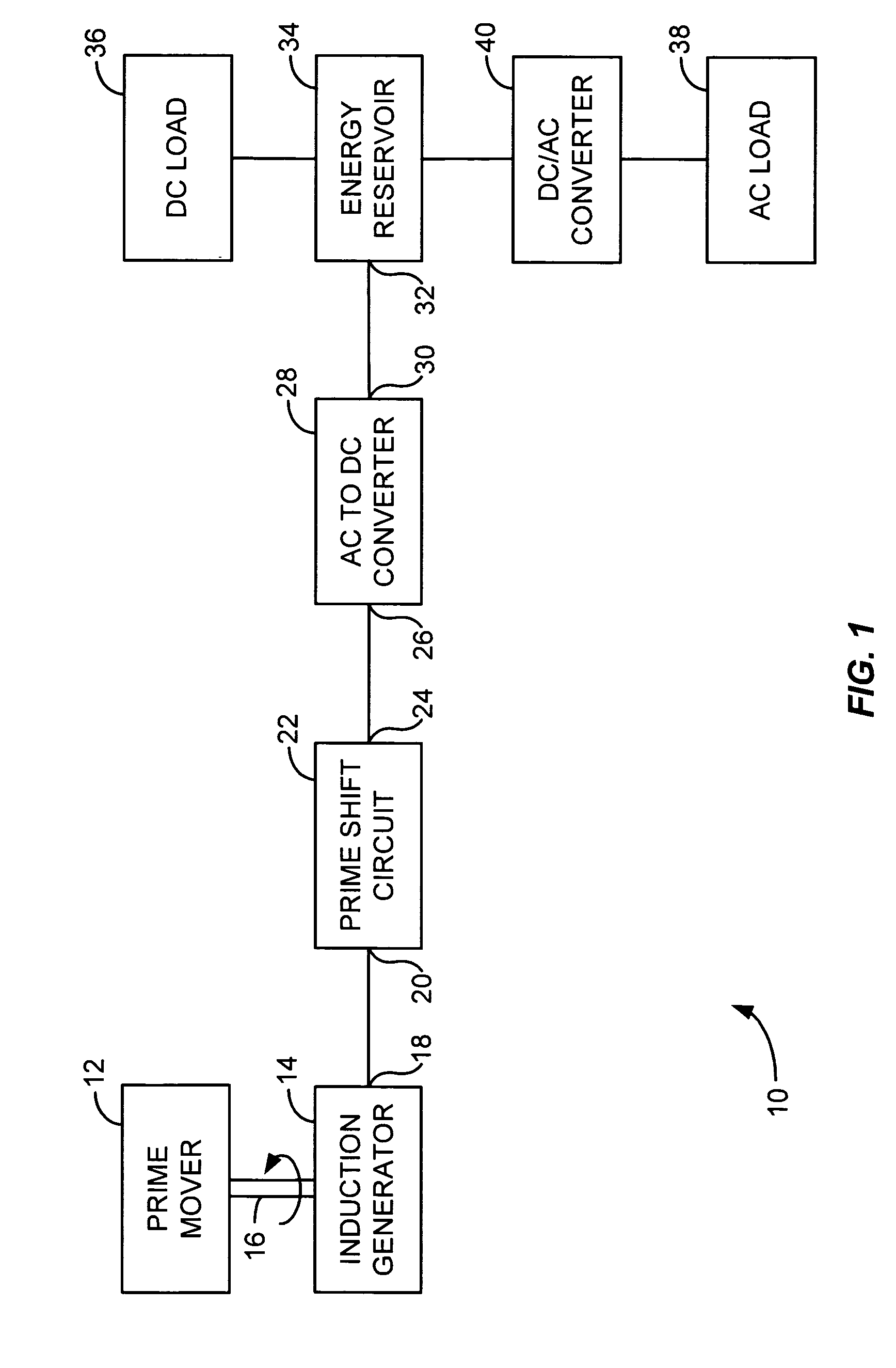
[0041]FIG. 1 illustrates an induction generator power supply 10 made according to the invention in a general, schematic form. Power supply 10 comprises a prime mover 12, such as a diesel engine or other internal combustion engine, connected to an induction generator 14 through a drive coupling 16. Induction generator 14 is sized, along with prime mover 12, to provide the average power required by the load. Other prime movers, such as external combustion engines, wind turbines or water turbines, could also be used. Induction generator 14 has a generator output 18 connected to the circuit input 20 of a phase shift circuit 22. Circuit 22 has a circuit output 24 connected to the converter input 26 of an AC to DC converter 28. Converter 28 has a converter output 30 connected to the reservoir input 32 of an energy reservoir 34. Energy reservoir 34 is typically a battery bank; other energy reservoirs, such as a capacitor bank, an inductor, a flywheel, elevated water storage and compressed ...


PUM


Abstract

A method for enhancing the operation of an electrical power supply includes selecting a prime mover having a chosen power rating. An induction motor having a first power rating at a rated speed and a second power rating at an overspeed is chosen. The overspeed may be at least about 10%, or at least about 25%, 50%, 75%, 10 to 300%, 25 to 300%, or 50 to 100%, greater than the rated speed. The induction motor may be chosen so that the second power rating is substantially the same as the chosen power rating of the prime mover. The induction motor is driven by the prime mover so that the induction motor acts as an induction generator. The system may also comprise a control module to monitor the performance of the power supply and to provide a throttle control signal in response to a control parameter signal. A circuit input of a phase shift circuit may be connected to a generator output. A converter input of an AC to DC converter may be connected to a circuit output of the phase shift circuit. A reservoir input of an energy reservoir may be connected to a converter output of the AC to DC converter.

Description

CROSS-REFERENCE TO RELATED APPLICATION[0001]This application is a continuation in part of U.S. patent application Ser. No. 10 / 255,995 filed Sep. 27, 2002, which application claims the benefit of provisional patent application No. 60 / 326,412 filed Oct. 1, 2001 and entitled “Induction Generator for AC or DC Applications”.BACKGROUND OF THE INVENTION[0002]This invention relates to the use of induction motors as generators and describes various means to make such use both practical and economical in applications such as hybrid electric vehicles and independent power generation.[0003]Electric vehicles have suffered from disadvantages of limited driving range and the time required to recharge batteries. The recent introduction of hybrid electric vehicles by major manufacturers has demonstrated that when an electric drivetrain is combined with an engine powered generator, there are significant benefits in terms of range, emissions levels and fuel economy and there is no recharging time sinc...

Claims


Application Information

Patent Timeline
Patent Type & Authority Patents(United States)
IPC IPC(8): H02P9/00H02J3/02H02J3/32H02J7/14H02J7/34H02J9/08H02M5/458H02M7/06
CPCH02J3/02H02J3/32H02J7/14H02J7/1415H02J7/1438H02J7/34H02M5/4585H02M7/06H02J9/08H02J3/322
Inventor COLLEY, BRUCE H.
Owner COLLEY BRUCE H
Why Eureka
Try Eureka