Disk drive determining a head-switch preheat period used to format a disk

a technology of a disk drive and a preheat period, applied in the field of disk drives, can solve problems such as slipping revolution

Inactive Publication Date: 2008-02-12
WESTERN DIGITAL TECH INC
View PDF35 Cites 156 Cited by
  • Summary
  • Abstract
  • Description
  • Claims
  • Application Information

AI Technical Summary

Benefits of technology

[0009]In one embodiment, the control circuitry measures a fly-height of the selected head from the read signal, and determines the head-switch preheat period in response to the measured fly-height. In one embodiment, the control circuitry extrapolates the head-switch preheat period from the measured fly-height.
[0010]In another embodiment, the control circuitry switches from a second one of the heads to the selected head during a head-switch operation, preheats the selected head for the head-switch preheat period, and accesses a data sector using the selected head after the head-switch preheat period and within a single revolution of the disk.
[0011]In yet another embodiment, the control circuitry formats the disk by mapping a logical block address to a physical block address corresponding to at least one of the data sectors. In one embodiment, the control circuitry maps a first and second consecutive logical block address. The first logical block address is mapped to a first physical block address corresponding to at least one of the data sectors on the first disk surface, and the second logical block address is mapped to a physical block address corresponding to at least one of the data sectors on the second disk surface, wherein the first physical block address is separated from the second physical block address by a distance corresponding to the head-switch preheat period.
[0012]In still another embodiment, the control circuitry adjusts the preheat period for preheating the head, rereads the test pattern from the disk using the selected head to generate a second read signal, and determines the head-switch preheat period in response to the read signal and the second read signal. In one embodiment, the control circuitry extrapolates the head-switch preheat period from the read signal and the second read signal.

Problems solved by technology

When the disk drive performs a head-switch to access a different disk surface, the preheat period required to heat the newly selected head can result in a slipped revolution if the head does not attain an acceptable fly-height prior to reaching the target data sector.

Method used


Image

  • Disk drive determining a head-switch preheat period used to format a disk
  • Disk drive determining a head-switch preheat period used to format a disk
  • Disk drive determining a head-switch preheat period used to format a disk

Examples


Embodiment Construction

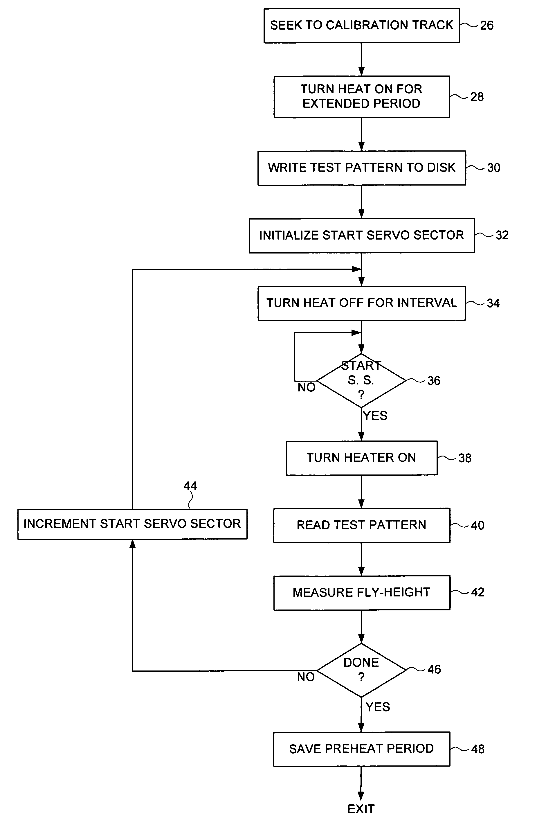
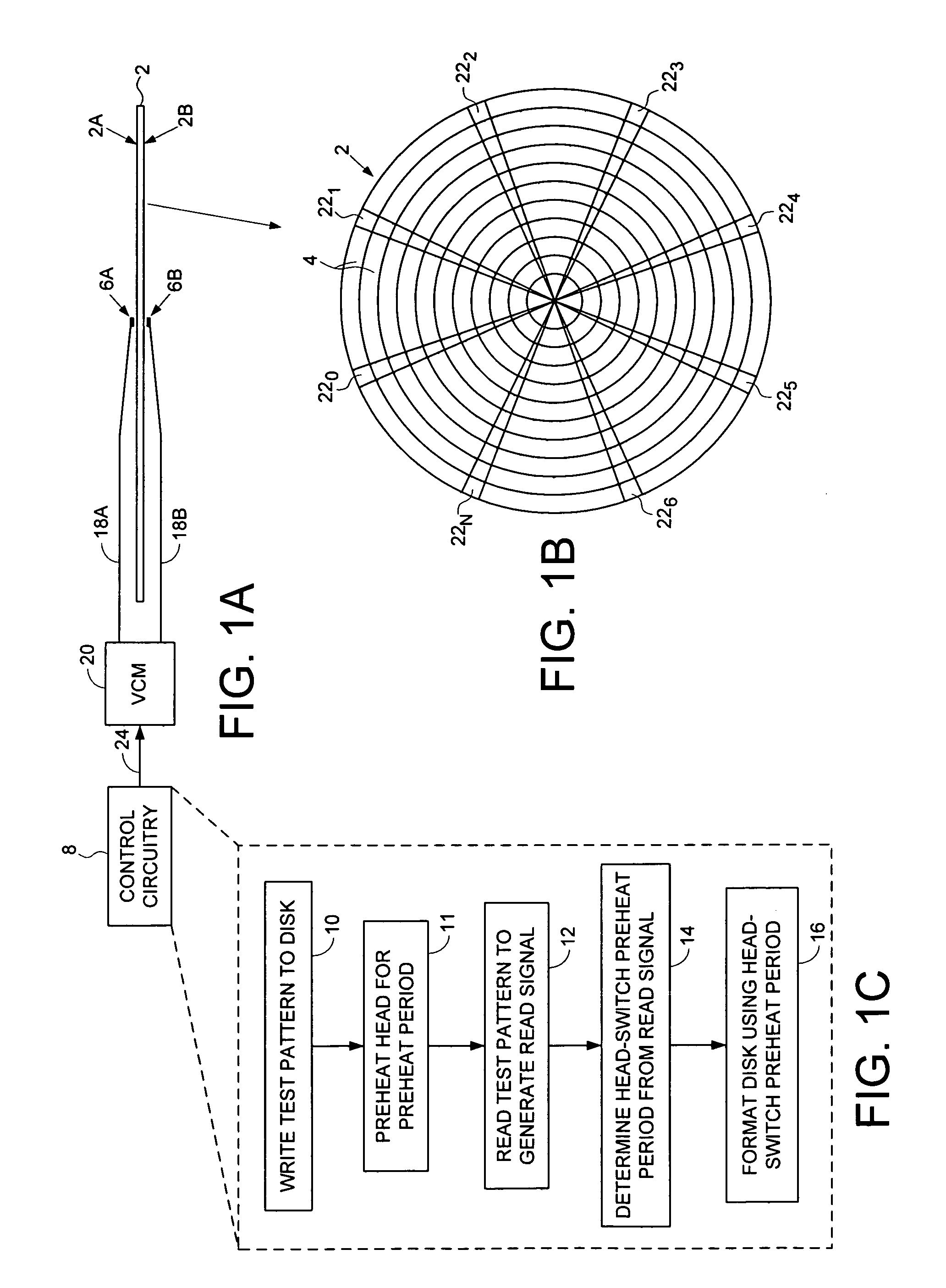
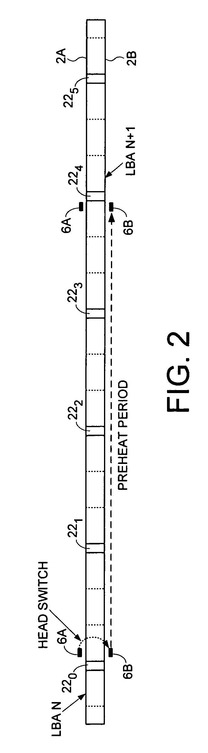
[0022]FIG. 1A shows a disk drive according to an embodiment of the present invention comprising a disk 2 having a plurality of tracks 4 (FIG. 1B), wherein each track 4 comprises a plurality of data sectors. The disk drive further comprises a plurality of heads, such as a top head 6A actuated over a top surface 2A of the disk and a bottom head 6B actuated over a bottom surface of the disk. Control circuitry 8 within the disk drive determines a head-switch preheat period used to format the disk 2. As shown in the flow diagram of FIG. 1C, the head-switch preheat period is calibrated by selecting one of the heads to write a test pattern to the disk at step 10, and then preheating the selected head at step 11 for a preheat period prior to reading the test pattern from the disk at step 12 to generate a read signal. At step 14 the head-switch preheat period is determined for the selected head in response to the read signal, and at step 16 the disk is formatted in response to the head-switc...


PUM


Abstract

A disk drive is disclosed comprising a disk having a plurality of tracks, wherein each track comprises a plurality of data sectors. The disk drive further comprises a plurality of heads, such as a top head and a bottom head. Control circuitry within the disk drive determines a head-switch preheat period used to format the disk. The head-switch preheat period is calibrated by selecting one of the heads to write a test pattern to the disk, and then preheating the selected head for a preheat period prior to reading the test pattern from the disk to generate a read signal. The head-switch preheat period is determined for the selected head in response to the read signal.

Description

BACKGROUND OF THE INVENTION[0001]1. Field of the Invention[0002]The present invention relates to disk drives for computer systems. More particularly, the present invention relates to a disk drive determining a head-switch preheat period used to format a disk.[0003]2. Description of the Prior Art[0004]In disk drives, a head is actuated radially over a disk in order to access a target track recorded on the disk. The head is attached to a distal end of an actuator arm which is rotated about a pivot by a voice coil motor during seek operations. As the disk rotates, an air bearing forms which causes the head to “fly” just above the disk surface while writing magnetic transitions during a write operation, or reading the magnetic transitions during a read operation. The head comprises a slider having an air bearing surface and an integrated transducer, such as a write coil and a magnetoresistive read element.[0005]Decreasing the distance between the transducer and disk surface (fly-height)...

Claims


Application Information

Patent Timeline
Patent Type & Authority Patents(United States)
IPC IPC(8): G11B5/09
CPCG11B5/455G11B20/182G11B5/59688G11B5/6011
Inventor SINGH, DALWINDERTHELIN, GREGORY B.NGUYEN, JONATHAN V.
Owner WESTERN DIGITAL TECH INC
Why Eureka
Try Eureka