Support structure of parts for vehicle

a technology for supporting structures and parts, applied in the direction of machine supports, furniture parts, cell components, etc., can solve the problems of deformation of the supporting rigidity of the fuse box, weight increase, and lowering so as to reduce the strength of the bracket, increase the thickness of the board, and reduce the effect of rigidity

Inactive Publication Date: 2008-02-19
NISSAN MOTOR CO LTD
View PDF17 Cites 44 Cited by
  • Summary
  • Abstract
  • Description
  • Claims
  • Application Information

AI Technical Summary

Benefits of technology

[0006]However, since the above support structure has a cantilever structure in which only the lower part of the bracket is connected to the tray, the strength of the bracket is lowered and the supporting rigidity of the fuse box is degraded. It is necessary to increase the board thickness in order to improve the rigidity of the bracket, but it causes weight increase.
[0008]The present invention was made in the light of the problem. An object of the present invention is to provide a support structure of parts for a vehicle, which enhances the mounting strength of parts such as a fuse box.

Problems solved by technology

However, since the above support structure has a cantilever structure in which only the lower part of the bracket is connected to the tray, the strength of the bracket is lowered and the supporting rigidity of the fuse box is degraded.
It is necessary to increase the board thickness in order to improve the rigidity of the bracket, but it causes weight increase.
Also, since a vertical rod for tying the battery to the tray is arranged in a gap between the bracket and the battery, the space efficiency of the engine compartment might be deteriorated.

Method used


Image

  • Support structure of parts for vehicle
  • Support structure of parts for vehicle
  • Support structure of parts for vehicle

Examples


Embodiment Construction

[0015]An embodiment of the present invention will be explained below with reference to the drawings, wherein like members are designated by like reference characters.

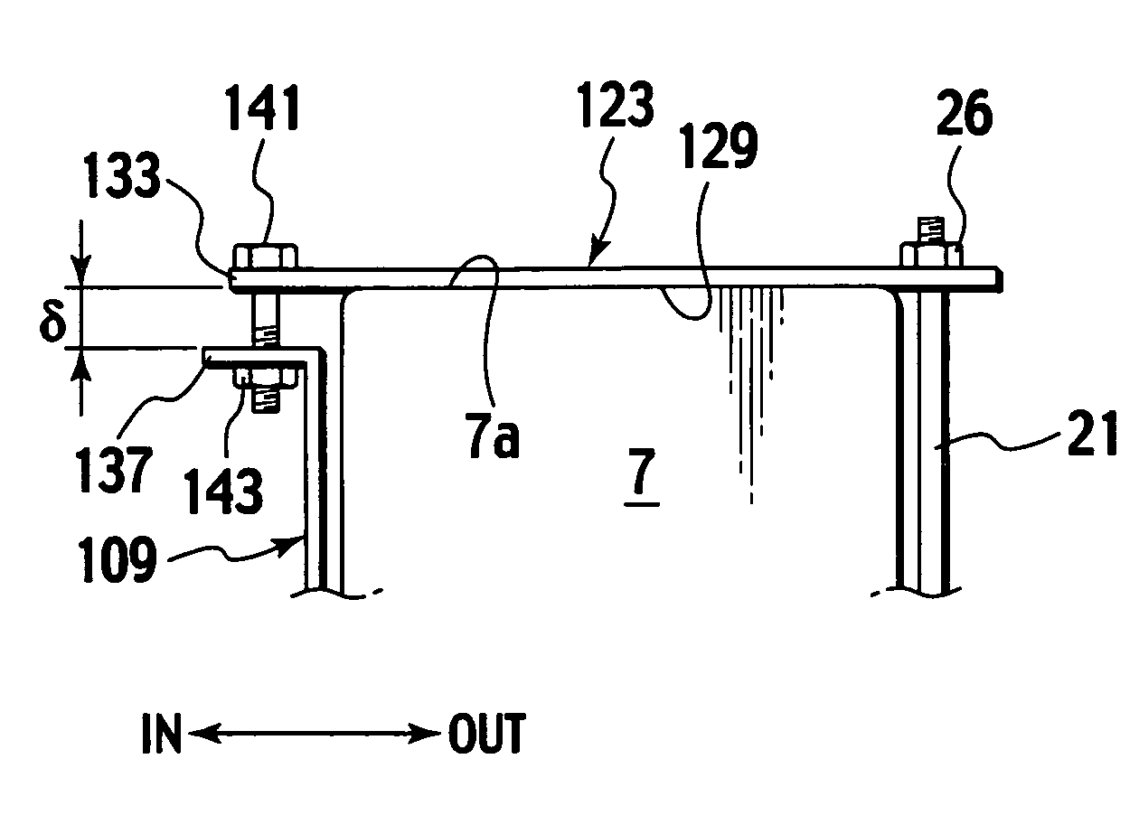
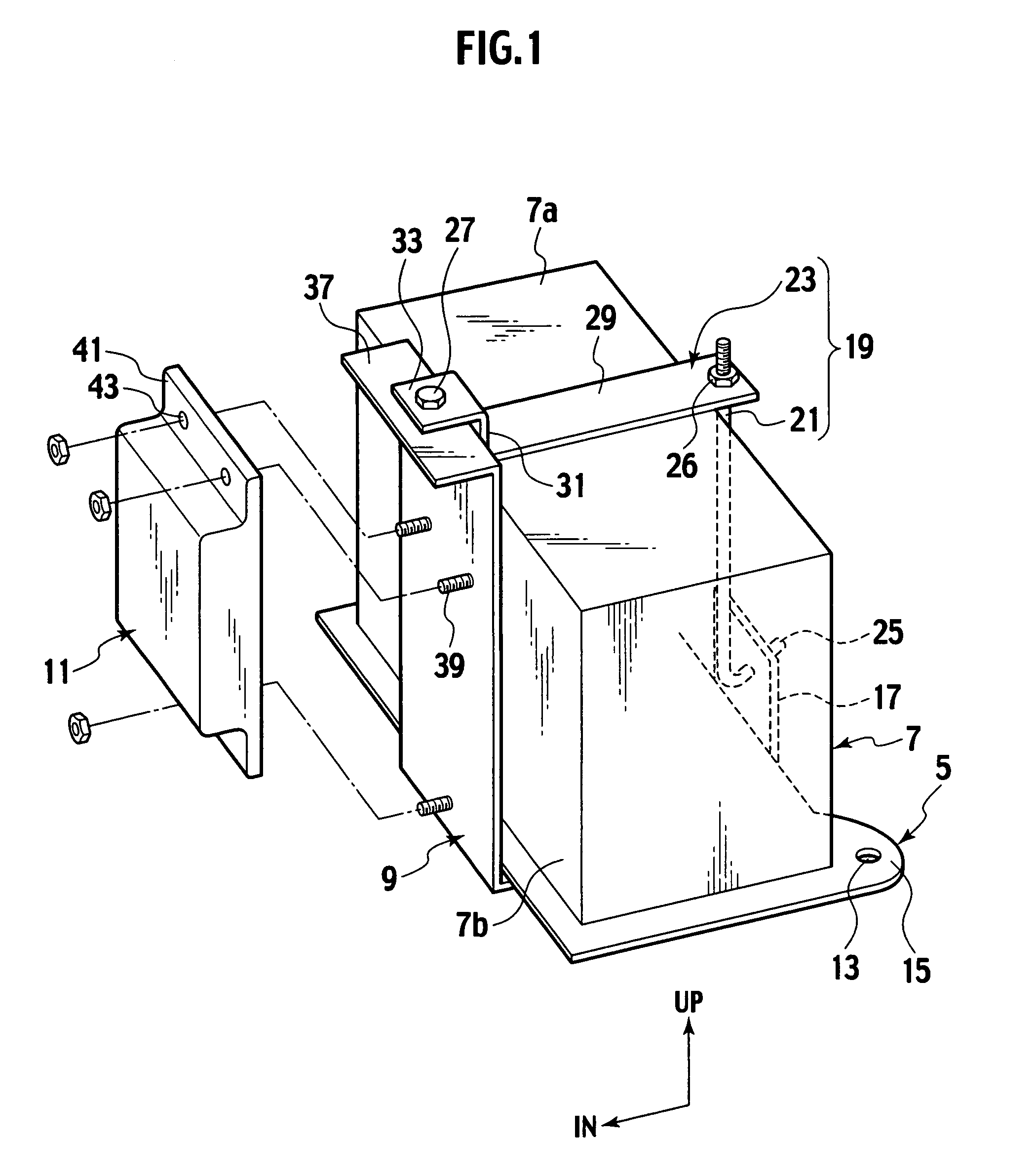
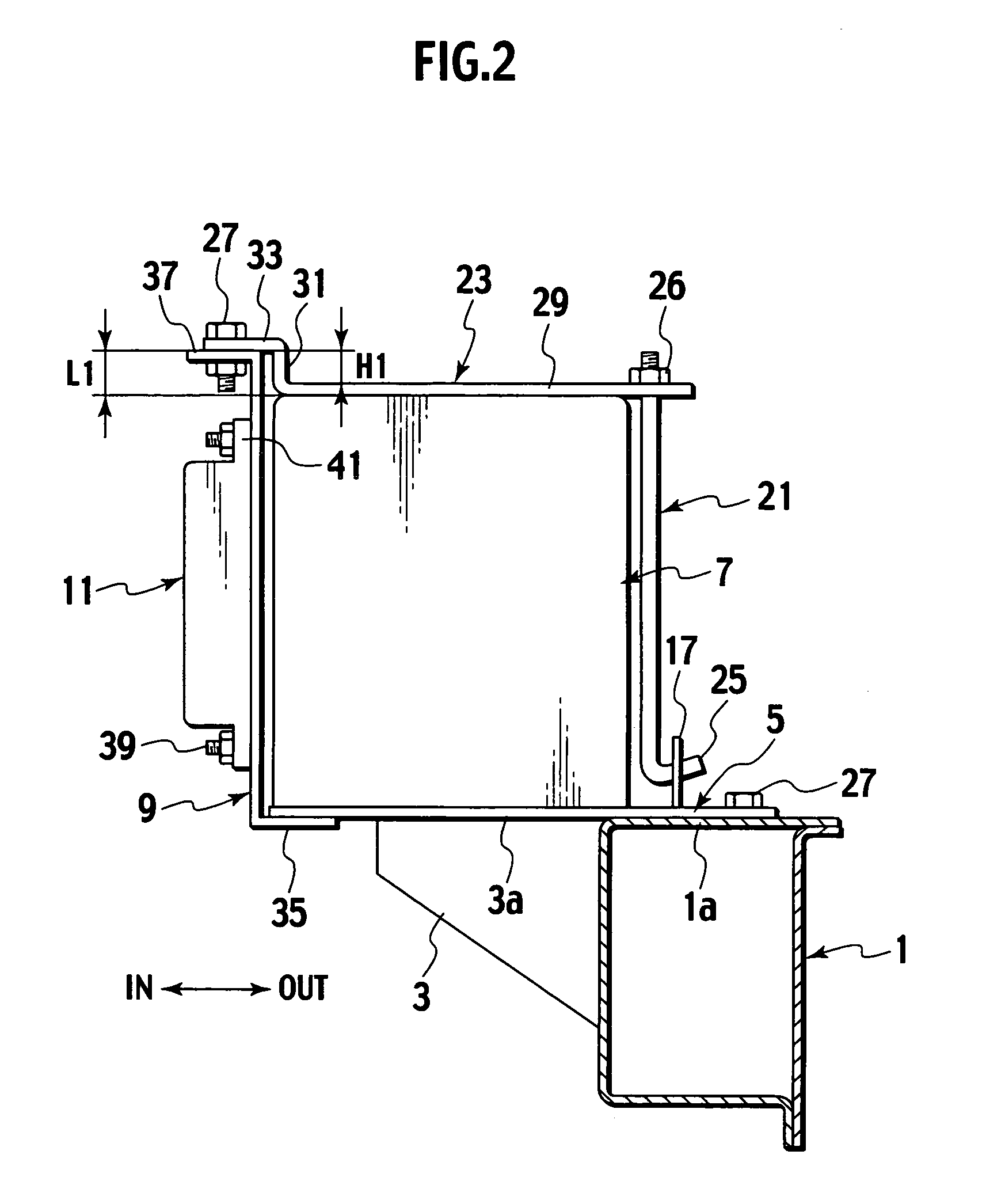
[0016]In an engine compartment of a vehicle, side members 1 are extended in the longitudinal direction of the vehicle on both right and left sides thereof. Each of the side members 1 is formed in the closed sectional structure having a rectangular shape in section, as shown in FIG. 2, and a support bracket 3 is provided on an inner side in the vehicle transverse direction of the side member 1. A top face 3a of this support bracket 3 is set at the same height as that of a top face 1a of the side member 1. And on these top faces 1a and 3a of the side member 1 and the support bracket 3, a tray 5 is provided to support a square-shaped heavy battery 7 (first part) using a retainer member 19. A fuse box 11 (second part) is supported on a bracket 9 arranged on the side of the battery 7.

[0017]The tray 5 has a top face formed in...


PUM


Abstract

A support structure of parts for a vehicle including: a tray fixed to a structural member of a vehicle body for mounting a first part thereto; a retainer member for retaining the first part on the tray; and a vertically extending support member for supporting a second part on the side of the first part. The support member is connected to the tray at a lower end thereof and to the retainer member at an upper end thereof.

Description

BACKGROUND OF THE INVENTION[0001]1. Field of the Invention[0002]The present invention relates to a support structure of parts for a vehicle, and particularly to a support structure of a battery and a fuse box mounted in an engine compartment of a vehicle.[0003]2. Description of Related Art[0004]A variety of parts for a vehicle including a battery, a fuse box, ABS actuator, electronic control unit, etc. are mounted in an engine compartment of the vehicle, in which the battery and the fuse box are mounted on the upper face of a front side member.[0005]The Japanese Patent Application Laid-open Publication No. 2002-29336 discloses a support structure in which a battery is mounted on a tray provided on a front side member, and a bracket is provided on the side of the battery and a fuse box is mounted on the bracket.SUMMARY OF THE INVENTION[0006]However, since the above support structure has a cantilever structure in which only the lower part of the bracket is connected to the tray, the s...

Claims


Application Information

Patent Timeline
Patent Type & Authority Patents(United States)
IPC IPC(8): F16M13/00B60R16/04B62D25/08A47B97/00B60R16/02H02G3/08
CPCB60R16/04
Inventor HIRAYU, TORU
Owner NISSAN MOTOR CO LTD
Why Eureka
Try Eureka