
Intervertebral disc replacement prosthesis

a technology for intervertebral discs and prostheses, which is applied in the field of devices for treating spine disorders, can solve problems such as pain or neurological deficit, premature degeneration, and increased risk of failure of adjacent discs

Inactive Publication Date: 2008-02-19
VANDERBILT UNIV
View PDF30 Cites 78 Cited by
  • Summary
  • Abstract
  • Description
  • Claims
  • Application Information

AI Technical Summary

Problems solved by technology

Any or a combination of these findings can lead to pain or neurological deficit.
While immobilization and a successful fusion may relieve the pain associated with nerve impingement, the long-term consequences of eliminating the motion of the intervertebral disc show a tendency toward increased risk of failure of the adjacent discs.
The lack of motion at the fusion site places increased biomechanical demands on the adjacent discs causing them to degenerate prematurely.
However, these devices are devoid of stiffness and stability and rely on the remaining spinal elements, such as the ligaments, muscles and remaining intervertebral disc tissue, namely the annulus fibrosis, for stability.
There are a risk of altering the spine's biomechanics by increasing the disc height past the normal range and / or a risk of damage to the annulus fibrosis.
If the disc space is not stretched enough an unstable spinal segment could result, possibly leading to pain and further injury.
In addition, this low stiffness places detrimentally high loads on supporting ligaments and muscles, particularly during movement involving torsional rotation of the spine.
Perfect alignment after insertion could be difficult.
Disadvantages of the mechanical spring disc types include attachment of the coiled springs to the metal end plates and associated wear at the attachment points.
These disc prostheses have their own inherent stiffness, but may not take into account that axial loads placed on the spine during activity are generally much larger than bending loads.
Therefore, these prostheses would either bottom out under axial loads and offer no response to bending loads, or be stiff enough to support the axial loads and thereby too stiff to flex under bending loads.
Therefore, a heretofore unaddressed need exists in the art to address the aforementioned deficiencies and inadequacies.

Method used


Image

  • Intervertebral disc replacement prosthesis
  • Intervertebral disc replacement prosthesis
  • Intervertebral disc replacement prosthesis

Examples


Embodiment Construction

[0050]The present invention is more particularly described in the following examples that are intended as illustrative only since numerous modifications and variations therein will be apparent to those skilled in the art. Various embodiments of the invention are now described in detail. Referring to the drawings, like numbers indicate like parts throughout the views. As used in the description herein and throughout the claims that follow, the meaning of “a,”“an,” and “the” includes plural reference unless the context clearly dictates otherwise. Also, as used in the description herein and throughout the claims that follow, the meaning of “in” includes “in” and “on” unless the context clearly dictates otherwise.

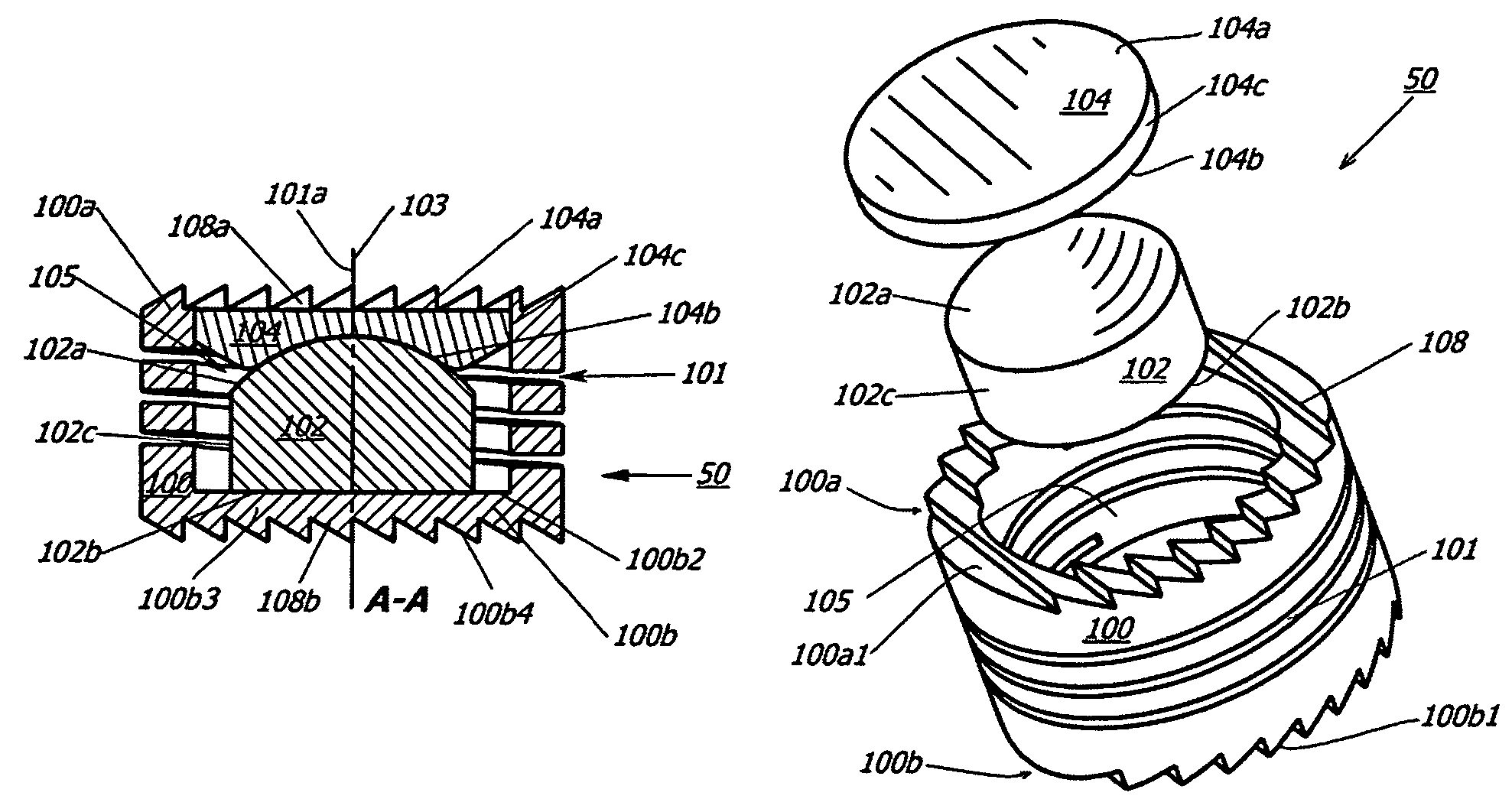
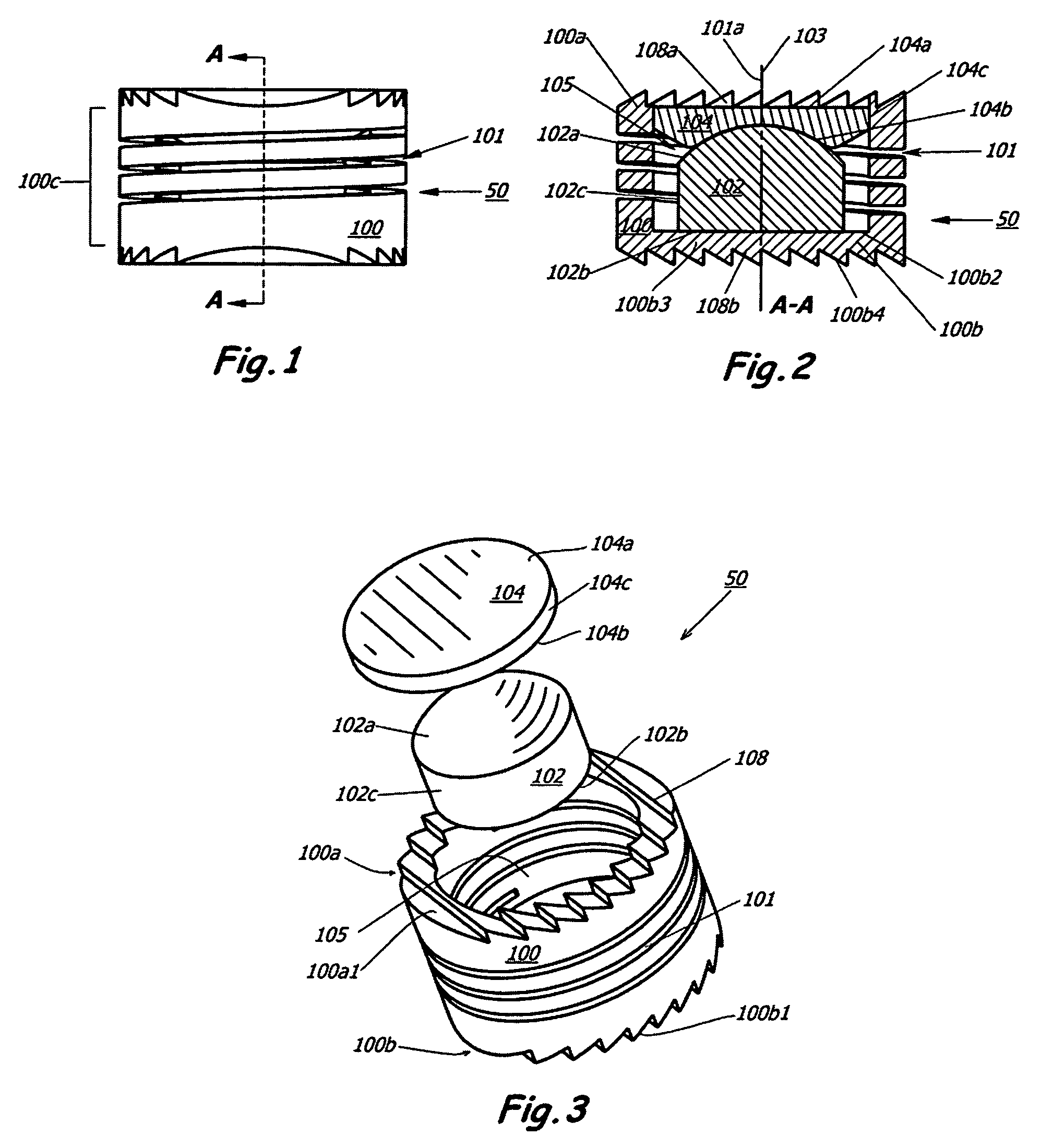
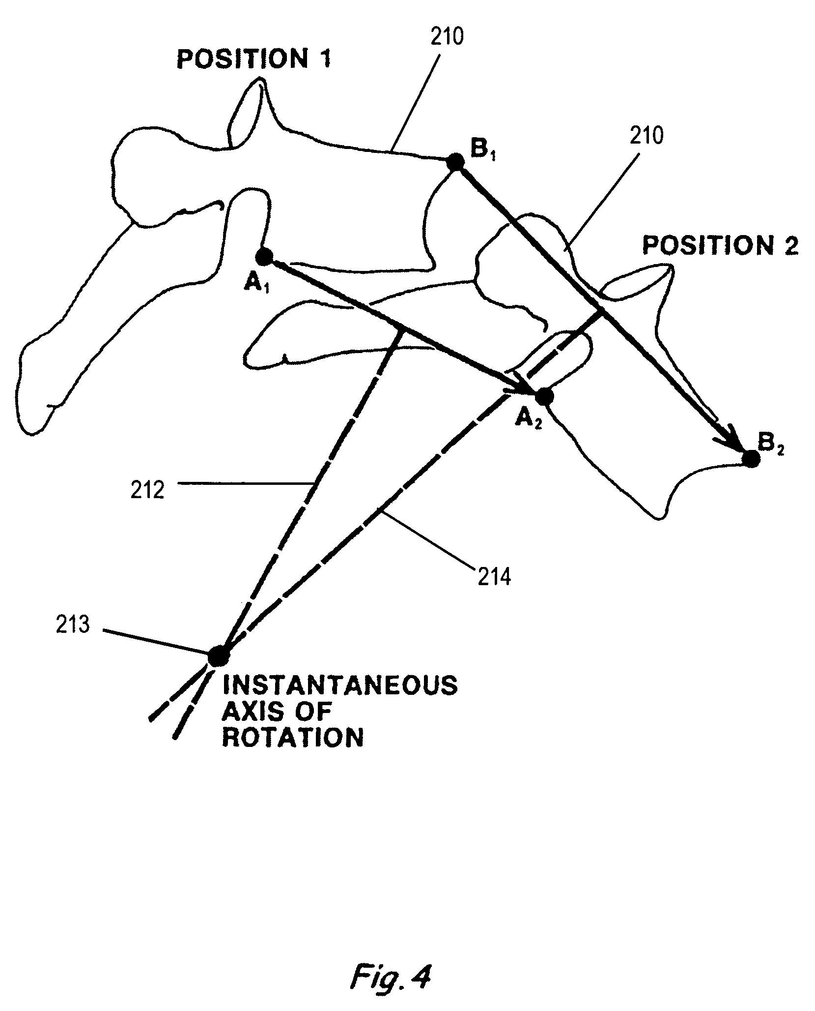
[0051]The description will be made as to the embodiments of the present invention in conjunction with the accompanying drawings 1-24. In accordance with the purposes of this invention, as embodied and broadly described herein, this invention, in one aspect, relates to an interv...


PUM

PropertyMeasurementUnit
thicknessaaaaaaaaaa
forceaaaaaaaaaa
resilientaaaaaaaaaa

Abstract

An intervertebral disc prosthesis for placement between a first vertebra and a second vertebra adjacent to the first vertebra. In one embodiment, the intervertebral disc prosthesis includes a resilient member, a first support member and a second support member. The first support member and the second support member are housed into the resilient member that is arranged, in use, to be secured to the first vertebra and the second vertebra, respectively. The intervertebral disc prosthesis can generate a coupled motion in more than one possible direction responsive to a possible movement of at least one of the first vertebra and the second vertebra, among the resilient member, the first support member and the second support member.

Description

CROSS-REFERENCE TO RELATED PATENT APPLICATION[0001]This application is a continuation-in-part of U.S. patent application Ser. No. 10 / 235,117, filed Sep. 5, 2002, now issued as U.S. Pat. No. 6,964,686, entitled “INTERVERTEBRAL DISC REPLACEMENT PROSTHESIS,” by Jeffrey D. Gordon, which is a continuation-in-part of and claims benefit of U.S. patent application Ser. No. 09 / 572,057, filed May 17, 2000, now issued as U.S. Pat. No. 6,579,321, entitled “INTERVERTEBRAL DISC REPLACEMENT PROSTHESIS,” by Jeffrey D. Gordon and John M. Dawson, and which itself claims the benefit, pursuant to 35 U.S.C. §119(e), of provisional U.S. patent application Ser. No. 60 / 134,500, filed May 17, 1999, the contents of which are incorporated herein in their entireties by reference, respectively.FIELD OF THE INVENTION[0002]The present invention generally relates to a device for treatment of spine disorders, and in particular to the utilization of an intervertebral disc prosthesis to perform one or more functions ...

Claims


Application Information

Patent Timeline
Patent Type & Authority Patents(United States)
IPC IPC(8): A61F2/44A61F2/00A61F2/30
CPCA61F2/442A61F2/4425A61F2/30742A61F2/30744A61F2/30767A61F2002/30113A61F2002/30125A61F2002/30133A61F2002/30225A61F2002/30227A61F2002/30228A61F2002/30233A61F2002/30242A61F2002/30289A61F2002/30365A61F2002/30405A61F2002/30451A61F2002/30492A61F2002/30507A61F2002/30565A61F2002/30571A61F2002/30576A61F2002/30578A61F2002/30594A61F2002/30596A61F2002/30649A61F2002/30769A61F2002/30772A61F2002/30795A61F2002/30841A61F2002/30906A61F2002/30909A61F2002/30968A61F2002/30975A61F2002/443A61F2220/0025A61F2220/0033A61F2220/0058A61F2230/0006A61F2230/0008A61F2230/0015A61F2230/0069A61F2230/0071A61F2230/0091A61F2310/00017A61F2310/00023A61F2310/00029A61F2310/00179A61F2310/0058A61F2310/00592
Inventor GORDON, JEFFREY D.SONG, JOHN K.
Owner VANDERBILT UNIV
Learn More