Optical disc apparatus

a technology of optical discs and trays, which is applied in the field of optical disc apparatuses, can solve the problems of very slow moving speed of the tray, achieve the effects of improving the smoothness of the drawing motion of the tray, improving the wear resistance, and improving the wear resistan

Inactive Publication Date: 2008-02-19
FUNAI ELECTRIC CO LTD
View PDF19 Cites 3 Cited by
  • Summary
  • Abstract
  • Description
  • Claims
  • Application Information

AI Technical Summary

Benefits of technology

[0006]A purpose of the present invention is to provide an optical disc apparatus, in which a blow sound due to collision of the stoppers of the tray and the chassis at the terminal position of drawing of the tray can be reduced with using no fine particle lubricant.
[0008]By such a configuration, kinetic energy of the tray is consumed to elastically deform the elastically deformable member when the elastically deformable member contacts the tray just before the terminal position of drawing of the tray, so that moving speed of the tray is largely decelerated. When the tray reaches to the terminal position of drawing the tray, the moving speed of the tray has become very slow. Consequently, blow sound due to collision of the tray and the main chassis is radically reduced, so that a quiet optical disc apparatus can be provided.
[0009]When the elastically deformable member is made of a material superior to wear resistance and having a coefficient of elasticity smaller than that of a material of the tray, it is no need to spread a fine particle lubricant to contacting portions of the tray and the elastically deformable member. Consequently, there is no fear to give bad influence to movement of the optical disc apparatus due to scattering of the powder ingredient of the lubricant in the inside of the apparatus. Smoothness of the drawing motion of the tray can be maintained in long-term use.

Problems solved by technology

When the tray reaches to the terminal position of drawing the tray, the moving speed of the tray has become very slow.

Method used


Image

  • Optical disc apparatus
  • Optical disc apparatus
  • Optical disc apparatus

Examples


Embodiment Construction

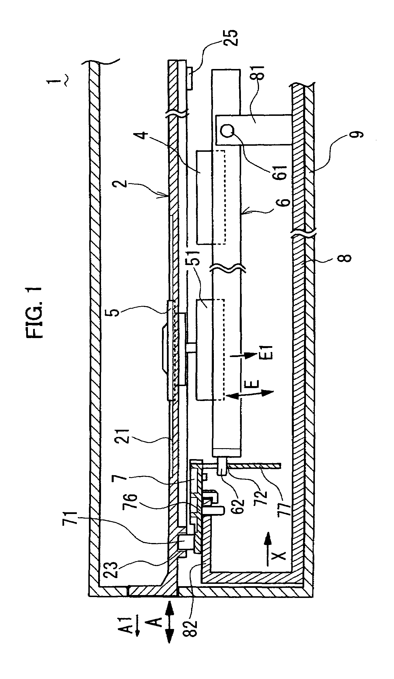
[0015]An optical apparatus in accordance with an embodiment of the present invention is described with reference to figures. FIG. 1 shows a constitution of an optical disc apparatus in accordance with the embodiment.

[0016]The optical disc apparatus 1 comprises a tray 2 which is used for loading an optical disc into an inside of the apparatus, a drive gear 3 (see FIG. 2) for moving the tray 2, an optical pick-up 4 which is used for writing and reading data on and from the optical disc, a revolving table 5 for supporting and rotating the optical disc, a movable chassis 6 on which the optical pickup 4 and the revolving table 5 are mounted, a cam slider 7 for rotationally swinging the movable chassis 6 around a pivot 61, a main chassis 8 on which the movable chassis 6, the cam slider 7, and so on are mounted, and a cover 9 for covering the above-mentioned elements.

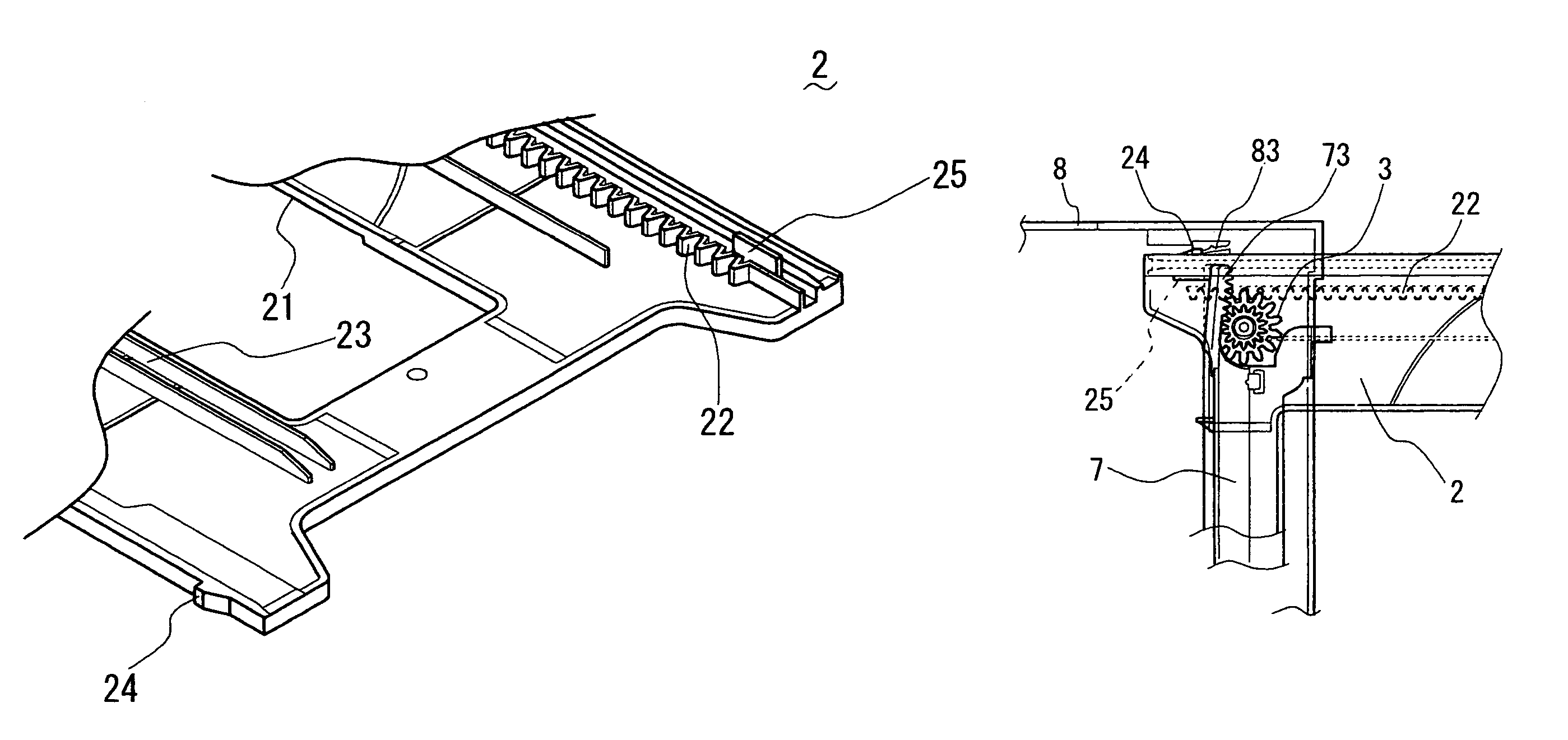
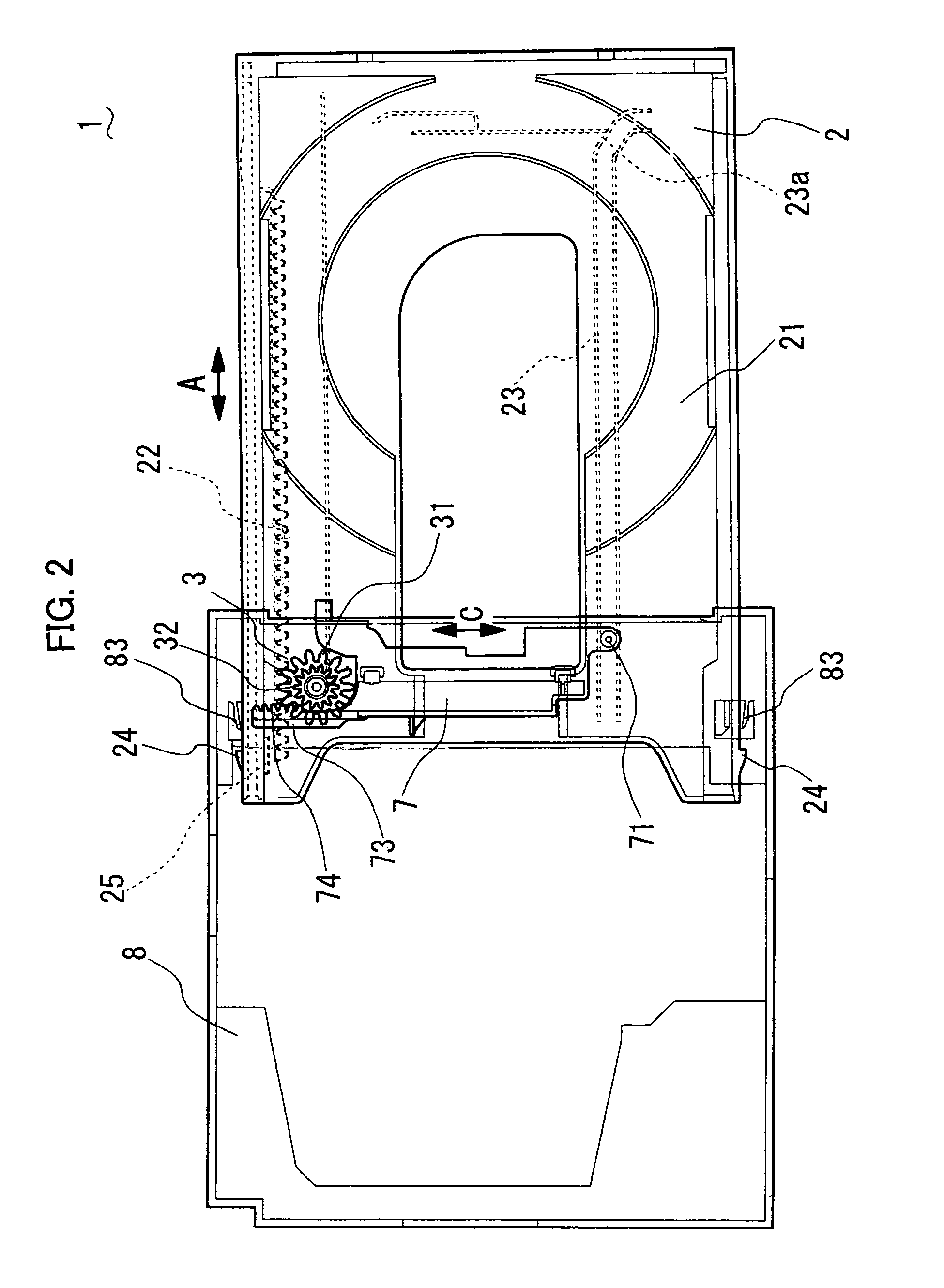
[0017]FIG. 2 shows a visualized constitution of an essential part of the optical disc apparatus 1, and FIG. 3 shows a struct...


PUM

PropertyMeasurementUnit
speedaaaaaaaaaa
elasticaaaaaaaaaa
wear resistanceaaaaaaaaaa

Abstract

In an optical disc apparatus, a harsh blow sound due to collision of first stoppers of a tray and third stoppers of a main chassis when the tray reaches to a terminal position of drawing thereof is reduced. When a second stopper of the tray contacts with the front end portion of a cam slider, the front end portion of the cam slider is elastically deformed so that moving speed of the tray is largely decelerated. Consequently, the blow sound due to contact of the first stoppers of the tray and the third stoppers of the main chassis is radically reduced.

Description

BACKGROUND OF THE INVENTION[0001]1. Field of the Invention[0002]The present invention relates to an optical disc apparatus used for reading and writing data with respect to an optical disc such as a DVD (Digital Versatile Disc), and so on, and especially relates to an optical disc apparatus having drawer mechanism of a tray on which an optical disc is disposed.[0003]2. Description of the Related Art[0004]In a conventional optical disc apparatus, for example, shown in laid-open bulletin of unexamined Japanese Patent Application No. 2002-334502, stoppers are formed on both of a tray and a chassis of the optical disc apparatus so as to stop the tray at a terminal position of the drawing of the tray. However, in such an optical disc apparatus, the stopper formed on the tray contacts to the stopper formed on the chassis at the terminal position of the drawing of the tray, and a harsh blow sound occurs. For preventing the occurrence of the harsh blow sound, an inclined plane, which is to ...

Claims


Application Information

Patent Timeline
Patent Type & Authority Patents(United States)
IPC IPC(8): G11B17/04G11B17/056G11B17/03
CPCG11B17/05
Inventor KOBAYASHI, TOMOHIRO
Owner FUNAI ELECTRIC CO LTD
Why Eureka
Try Eureka