
Thin layer electrochemical cell with self-formed separator

a self-formed separator and electrochemical cell technology, applied in the direction of non-aqueous electrolyte cells, cell components, sustainable manufacturing/processing, etc., can solve the problems of battery inoperative, temperature dependent operation, battery swelling, etc., and achieve the effect of reducing the number of manufacturing steps

Inactive Publication Date: 2008-02-26
POWER PAPER
View PDF21 Cites 54 Cited by
  • Summary
  • Abstract
  • Description
  • Claims
  • Application Information

AI Technical Summary

Benefits of technology

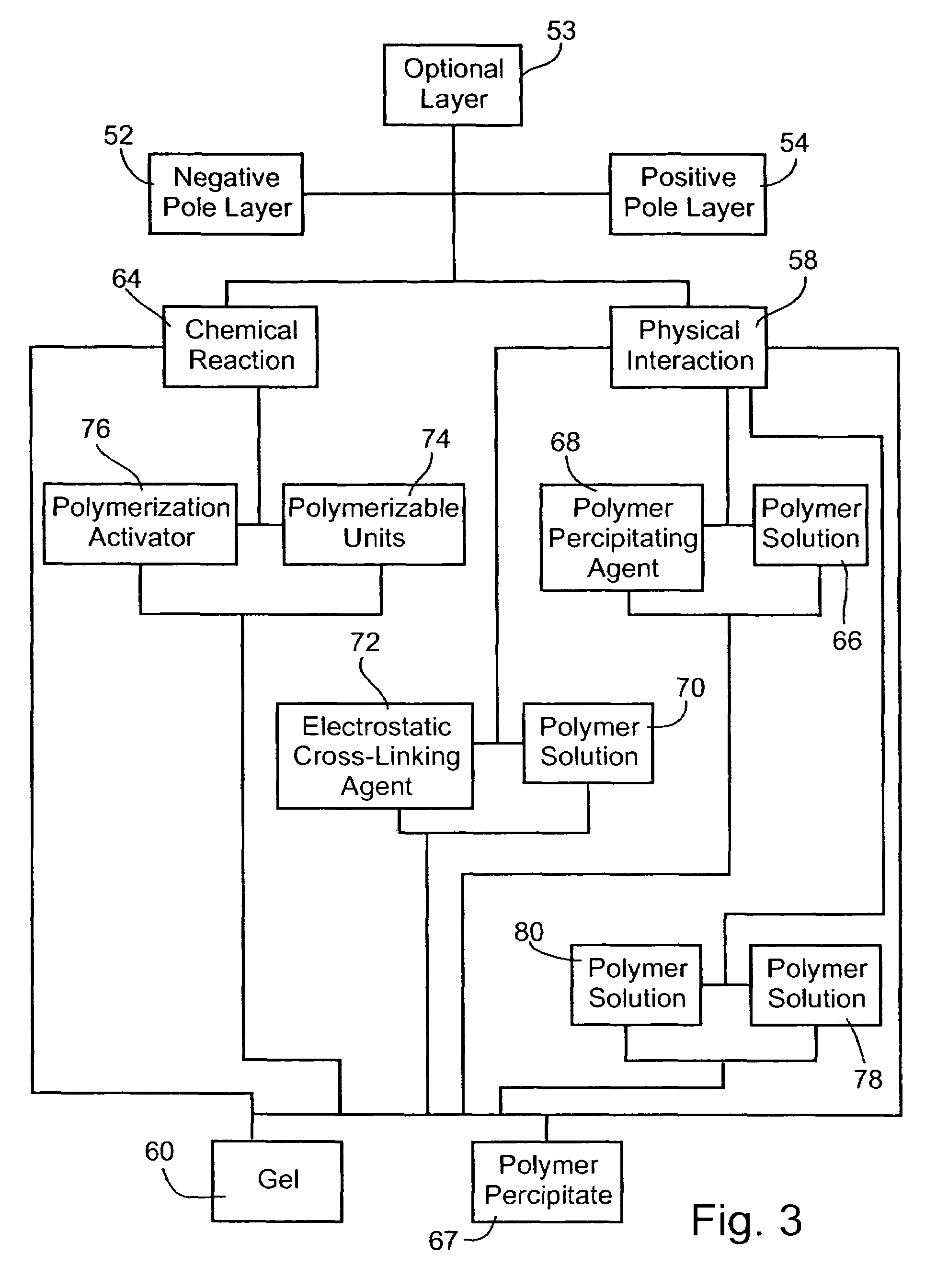
"The present invention provides improvements to flexible, thin layer, open liquid state electrochemical cells by eliminating the need for a separate separator layer between the pole layers. Instead, an interfacial separator layer is formed between the pole layers upon interaction between the ingredients in the negative and positive pole layers or an optional layer disposed between them. The interfacial separator layer can be formed through a physical interaction or chemical reaction between the ingredients. The resulting cell is deliquescent and keeps the pole layers wet at all times, while also providing ionic conductivity. The invention provides a method for forming the electrochemical cell by contacting the pole layers with an optional layer interposed between them. The ingredients can be selected from a variety of polymers and precipitating agents. The interfacial separator layer can be formed through a physical interaction or chemical reaction between the ingredients. The technical effects of the invention include improved flexibility, reduced thickness, and increased efficiency of the electrochemical cell."

Problems solved by technology

However, they suffer major disadvantages when compared with liquid state batteries since, due to limited diffusion rates of charges through a solid, their operation is temperature dependent to a much larger extent, and many operate well only under elevated temperatures.
Being closed cells, these batteries tend to swell upon storage due to evolution of gases.
This is a fatal problem in thin layer batteries having no mechanical support, because the pressure imposed by the accumulated gases leads to separation of the layers, making the battery inoperative.
However, the polymer is limited in its effectiveness and the mercury is environmental hazardous.
This, in turn, is limiting in the sense that (i) it calls for at least three manufacturing steps; and (ii) the contact between the layers is typically less than optimal.

Method used


Image

  • Thin layer electrochemical cell with self-formed separator
  • Thin layer electrochemical cell with self-formed separator
  • Thin layer electrochemical cell with self-formed separator

Examples


Embodiment Construction

[0061]The present invention is of thin layer, liquid state electrochemical cells that include self-formed separators and methods for their production.

[0062]The principles and operation of the electrochemical cell and the method according to the present invention may be better understood with reference to the drawings and accompanying descriptions.

[0063]Before explaining at least one embodiment of the invention in detail, it is to be understood that the invention is not limited in its application to the details of construction and the arrangement of the components set forth in the following description or illustrated in the drawings. The invention is capable of other embodiments or of being practiced or carried out in various ways. Also, it is to be understood that the phraseology and terminology employed herein is for the purpose of description and should not be regarded as limiting.

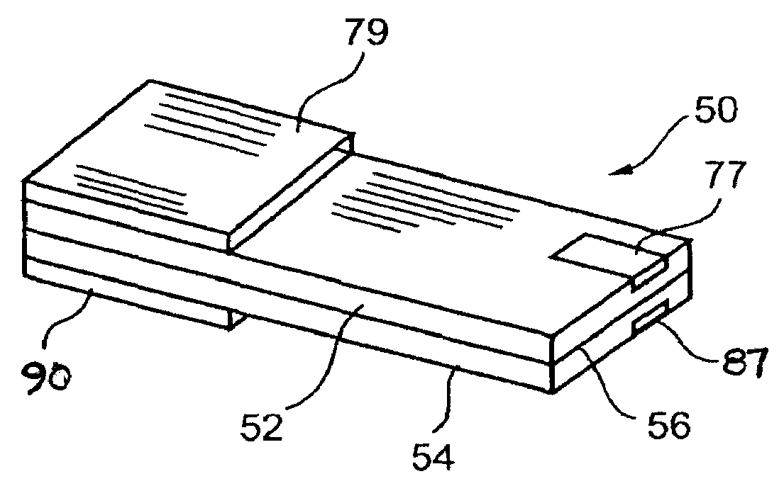
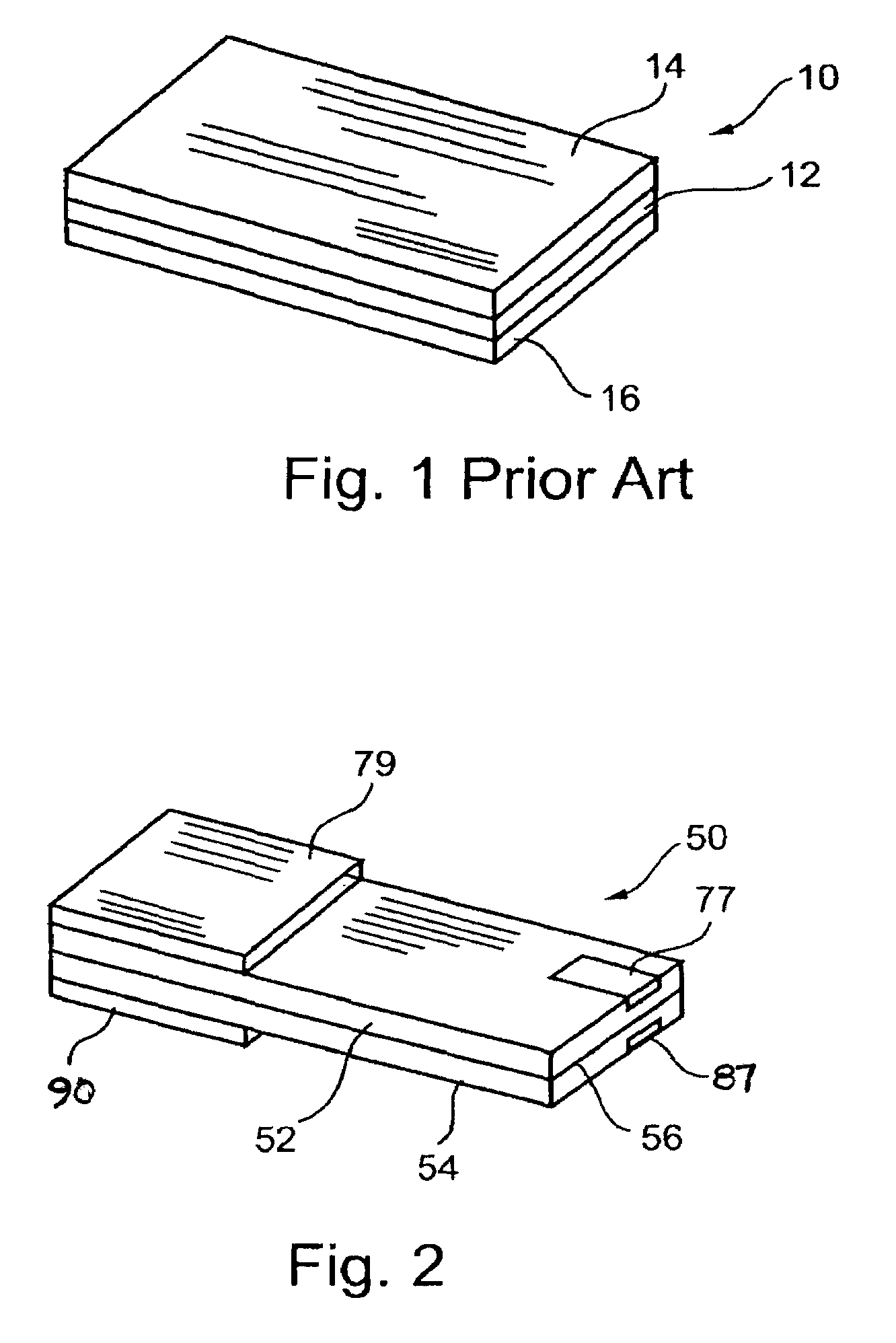
[0064]Reference is now made to FIG. 2, which illustrates a flexible, thin layer, open electrochemical...


PUM

PropertyMeasurementUnit
thicknessaaaaaaaaaa
temperatureaaaaaaaaaa
ionic conductivityaaaaaaaaaa

Abstract

A method of forming an electrochemical cell is disclosed. The method comprises contacting a negative pole layer and a positive pole layer one with the other or with an optional layer interposed therebetween. The pole layers and the optional layer therebetween are selected so as to self-form an interfacial separator layer between the pole layers upon such contacting.

Description

[0001]This is a continuation-in-part of U.S. patent application Ser. No. 09 / 931,943, filed Aug. 20, 2001, now U.S. Pat. No. 7,022,431.FIELD OF THE INVENTION[0002]The present invention relates to thin layer, liquid state electrochemical cells with, preferably, an open configuration, that are used as battery power sources by converting chemical energy to electrical energy, and particularly to such a cell with a liquid electrolyte and self-formed porous separator layer between negative and positive pole layers.BACKGROUND OF THE INVENTION[0003]There are two broad classes of batteries: liquid state batteries, i.e., those with a liquid or wet electrolyte, and solid state batteries, i.e., those with an electrolyte in a solid state. Solid state batteries have advantages over liquid state batteries in that they inherently do not dry out and do not leak. However, they suffer major disadvantages when compared with liquid state batteries since, due to limited diffusion rates of charges through ...

Claims


Application Information

Patent Timeline
Patent Type & Authority Patents(United States)
IPC IPC(8): H01M2/14H01M10/04H01M6/06H01M6/12H01M6/18H01M6/22H01M6/40H01M50/403
CPCH01M2/145H01M2/1673H01M6/12H01M6/40H01M10/0436H01M6/22H01M2/0292H01M6/181H01M6/188Y10T29/49108H01M10/04H01M2300/0002H01M2300/0085Y02E60/10H01M50/124H01M50/1245H01M50/403H01M50/46Y02P70/50
Inventor LUSKI, SHALOMSHCHORI, EHUDNITZAN, ZVI
Owner POWER PAPER
Learn More