

Twin fin fairing
a twin fin and fairing technology, applied in the field of fairing, can solve the problems of threatening the structural integrity of the riser, the riser, the pipeline, etc., and reducing the energy transfer from the current to the riser, so as to reduce the vibration of the vortex and reduce the vibration. , the effect of reducing the vibration
Active Publication Date: 2008-03-04
SEAHORSE EQUIP
View PDF18 Cites 20 Cited by
- Summary
- Abstract
- Description
- Claims
- Application Information
AI Technical Summary
Benefits of technology
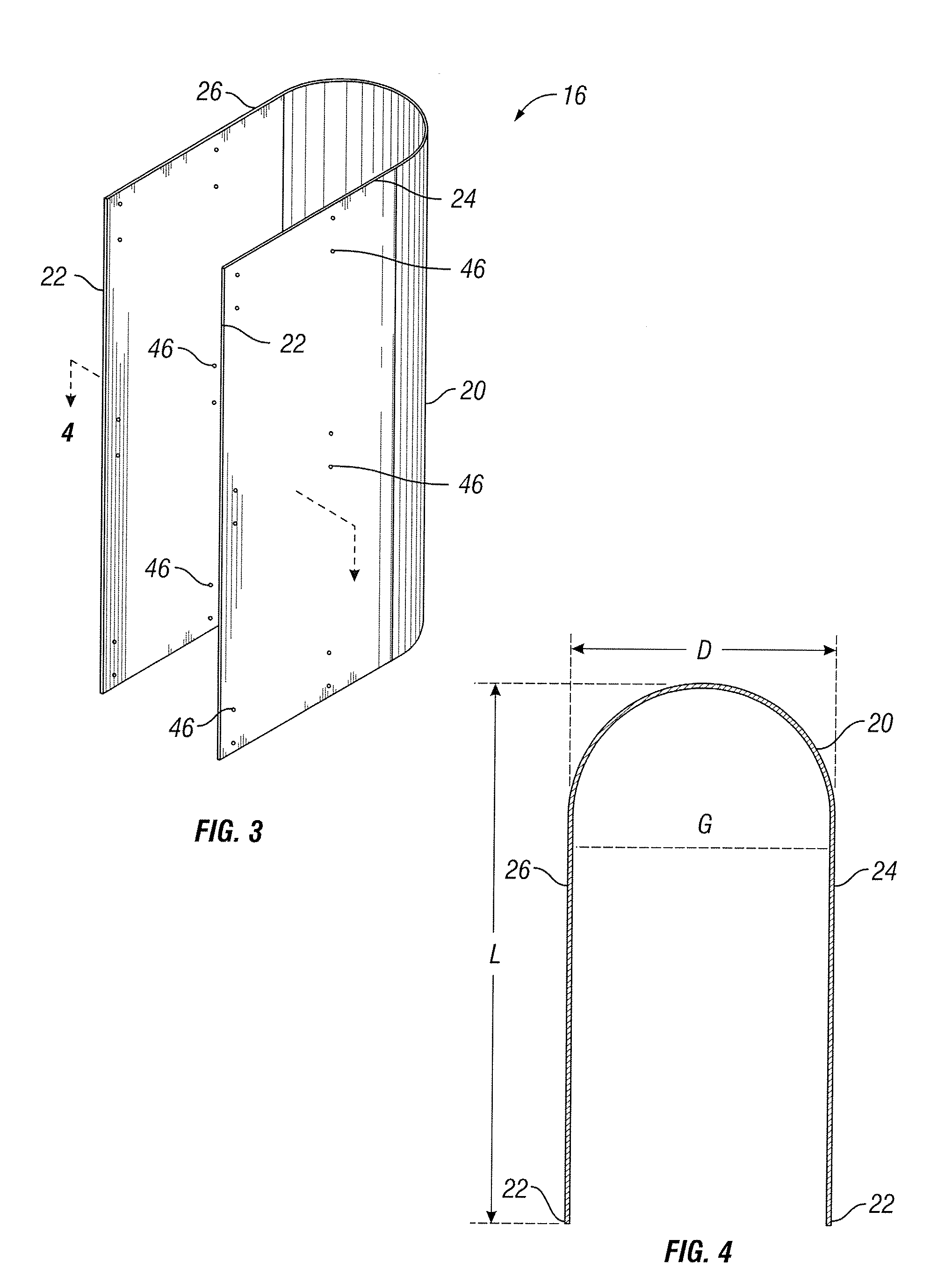
[0012]The subject invention is directed to a fairing for the reduction of vortex-induced vibration, the minimization of drag and the elimination of galloping about a substantially cylindrical element immersed in a fluid medium. The fairing has a U-shaped cylindrical shell with opposing edges defining a longitudinal gap and parallel fins extending outwardly from the opposing edges of the shell, the parallel fins being positioned so as to reduce vortex-induced vibration, minimize drag and to eliminate the phenomenon of galloping on the cylindrical element. The fairing has a length to diameter ratio of 1.5 to 2.50 and preferably a ratio of 1.75 to 2.0 where the length is measured from the leading nose of the fairing body to the end of the fins, and the diameter is the diameter of the center of the circle defining the shell.
[0018]The invention also includes a fairing system for the reduction of vortex-induced vibration and the minimization of drag about a substantially cylindrical element immersed in a fluid medium. The fairing system has a plurality of fairings having U-shaped cylindrical shells, each shell having opposing edges defining a longitudinal gap. Parallel fins extending outwardly from the opposing edges of each of the plurality of shells, the parallel fins being positioned so as to reduce vortex-induced vibration, minimize drag and the elimination of galloping on the cylindrical element. The fairing includes means for securing each of the plurality of fairings around the cylindrical element.
Problems solved by technology
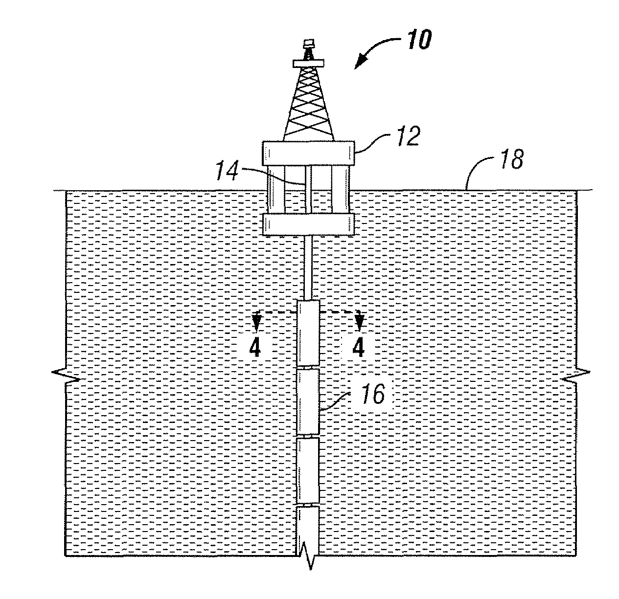
While those waters may bring the reserves they seek, the offshore producers are also faced with stronger currents threatening the structural integrity of their risers, pipelines, and other elongated and cylindrical components involved in oil and gas production.
If the frequency of this harmonic load is near the resonant frequency of the riser, large vibrations transverse to the current can occur.
This results in more energy transfer from the current to the riser, and hence more drag.
The movement of oil and gas exploration, development and production into deep and ultra-deep waters has created unique engineering challenges requiring innovative engineering solutions.
One particular challenge is the vortex-induced-vibrations (VIV) of long drilling and production risers.
The resulting vibration increases drag, reduces fatigue life and left unchecked may lead to the failure of the marine element or its supports.
Strakes and shrouds can be effective regardless of the current orientation, but they tend to increase the drag acting on the riser.
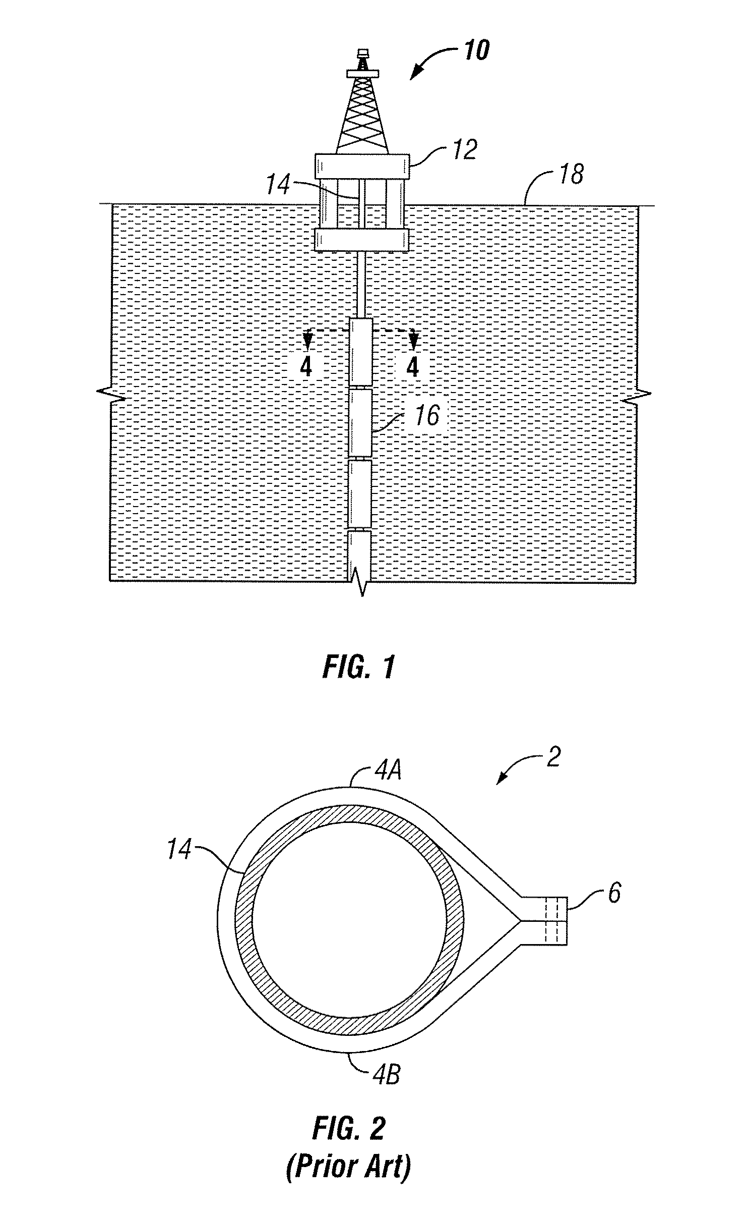
While fairings can be effective for reducing VIV, a number of problems still exist with the prior art fairings.
As illustrated in the prior art, fairings have become more and more complex in design, they often require a large number of parts, and as such, they have become more costly to produce and maintain.
Further, the use of such fasteners adds to the cost and labor associated with the fairing's use.
Additionally, corrosion and marine growth frequently causes the rotational elements of a fairing to seize up so that it can no longer rotate and properly align with the current.
Such a concern has often resulted in fairings being used only on risers or other components that remain on the risers only a short period of time, leaving those in the industry to rely upon less effective VIV reduction means such as fixed-fin vortex strakes for more permanently fixed components.
While conventional teardrop fairings are effective in reducing both drag and VIV, users report that these devices are subject to a “galloping” motion.
One of the problems of installing fairings in this manner is that when the fins of the fairing rotate over the rollers on the ramp, the fins frequently become damaged by the rollers.
Method used
View moreImage
Smart ImageViewing Examples

Examples
Embodiment Construction
[0048]The present invention is directed to rotating fairings that include specifically placed fins for the reduction of vortex-induced vibration (“VIV”) on pipes or other structural components immersed in fluid. As discussed above, when a solid object is exposed to fluid flows vibration results from vortices shed off the object when the fluid flows by it. The flow pattern around a cylinder can be characterized by the Reynolds Number (Re) of the incident flow and the location where flow separates from the cylinder surface which depends on whether the boundary layer is turbulent or laminar. In the subcritical range, the Reynolds number range is 300
Login to View More PUM
 Abstract
A fairing for the reduction of vortex-induced vibration and the minimization of drag about a substantially cylindrical element immersed in a fluid medium. The fairing also eliminates the galloping phenomenon typically associated with a teardrop-shaped fairing. The fairing having a U-shaped cylindrical shell with opposing edges defining a longitudinal gap and parallel fins extending outwardly from the opposing edges of the shell, the parallel fins being positioned so as to reduce vortex-induced vibration, minimize drag and to eliminate the galloping phenomenon on the cylindrical element. Preferably, the length to diameter ratio of the fins is 1.5 to 2.50.
Description
TECHNICAL FIELD[0001]The present invention relates generally to the reduction of vortex-induced vibration (“VIV”) and more particularly to a fairing used for the reduction of VIV on pipes or other structural components immersed in a fluid.BACKGROUND OF THE INVENTION[0002]Exploration for oil and natural gas reserves led drillers offshore many years ago and as offshore exploration continues, offshore producers find themselves in deeper and deeper waters. While those waters may bring the reserves they seek, the offshore producers are also faced with stronger currents threatening the structural integrity of their risers, pipelines, and other elongated and cylindrical components involved in oil and gas production.[0003]Stresses on the pipes or other structural components immersed in fluid, such as drilling risers, production risers, pipelines, structural tendons, etc. greatly increase as the velocity of the current increases and the stresses are magnified as the depth of the water and le...
Claims
Login to View More Application Information
Patent Timeline
 Patent Type & AuthorityPatents(United States)
IPC IPC(8): F15D1/10
CPCE21B17/01F15D1/10F16L1/12F16L1/123
InventorMASTERS, RODNEY H.MASTERS, RANDY W.SYKES, MICHAELLEVERETTE, STEVEN J.SCHAUDT, KENNETH J.
OwnerSEAHORSE EQUIP