Turbo compressor

a compressor and turbine technology, applied in the field of turbine compressors, can solve the problems of reducing compression efficiency and reducing compression efficiency, and achieve the effect of improving compression efficiency

Inactive Publication Date: 2008-03-04
SAMSUNG ELECTRONICS CO LTD
View PDF14 Cites 27 Cited by
  • Summary
  • Abstract
  • Description
  • Claims
  • Application Information

AI Technical Summary

Benefits of technology

[0014]Accordingly, an aspect of the present invention provides a turbo compressor improved in compression efficiency.

Problems solved by technology

The leakage flow thereby decreases compression efficiency.
However, in the conventional turbo compressor, the plurality of backflow prevention grooves are provided in the shroud in order to eliminate the backflow from the diffuser to the gas suction part, but there is nothing to eliminate the leakage flow, so that the compression efficiency is decreased.
That is, because the leakage flow flows along the rotating direction of the impeller, the backflow prevention grooves formed along the rotating direction of the impeller cannot eliminate the leakage flow.

Method used


Image

  • Turbo compressor
  • Turbo compressor
  • Turbo compressor

Examples


first embodiment

[0031]As shown in FIGS. 4 through 7, a turbo compressor 1 according to the present invention comprises a driving motor 20 mounted in a motor casing 10; first and second impellers 40 and 50 connected to a rotating shaft 5 of the driving motor 20 and rotating integrally with the rotating shaft 5; a pair of shrouds 60 shrouding and spaced apart from the first and second impellers 40 and 50; first and second gas suction part 45 and 55 communicating with a first side of each shroud 60 and through which gas, such as a refrigerant, is introduced into the impellers 40 and 50; first and second diffusers 47 and 57, as a gas discharger, communicating with a second side of each shroud 60 and transforming kinetic energy of the gas drawn by the impellers 40 and 50 into compression energy; and a gas connector 48 between the first diffuser 47 and the second gas suction part 55 and introducing the gas diffused by the first diffuser 47 into the second gas suction part 55. Further, the second diffuser...

second embodiment

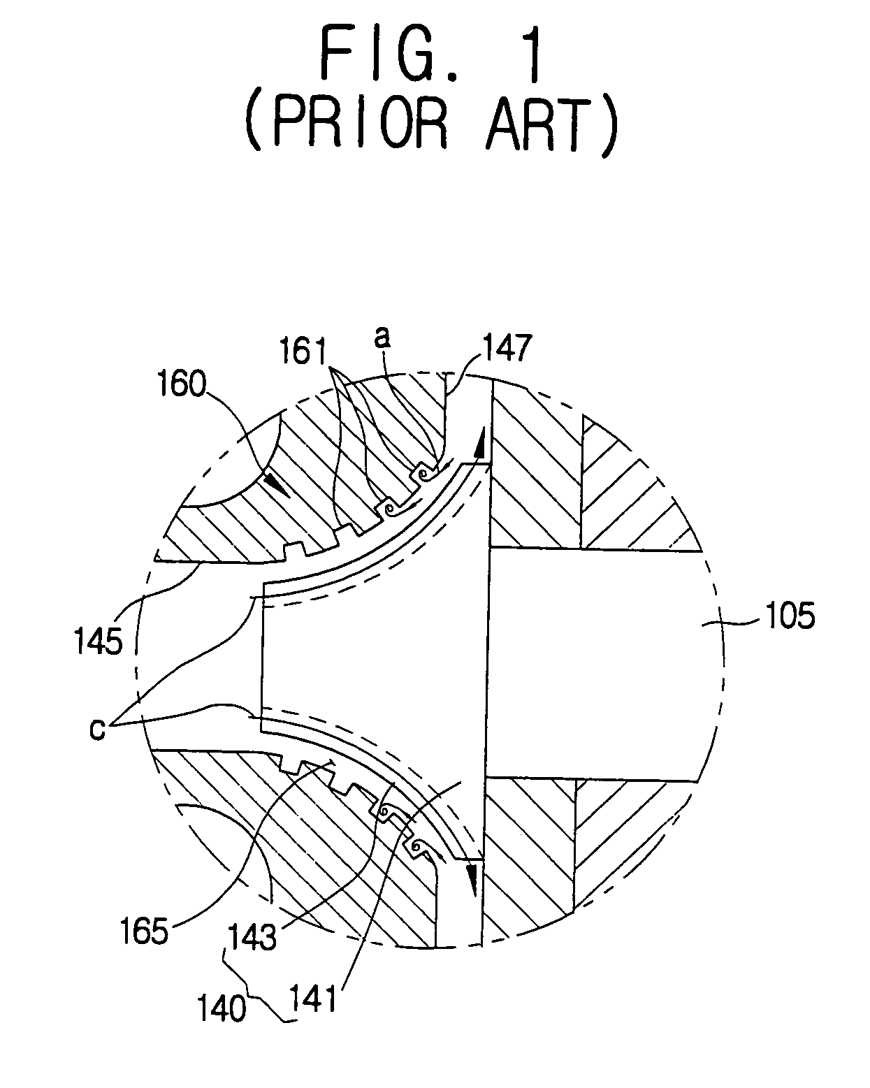
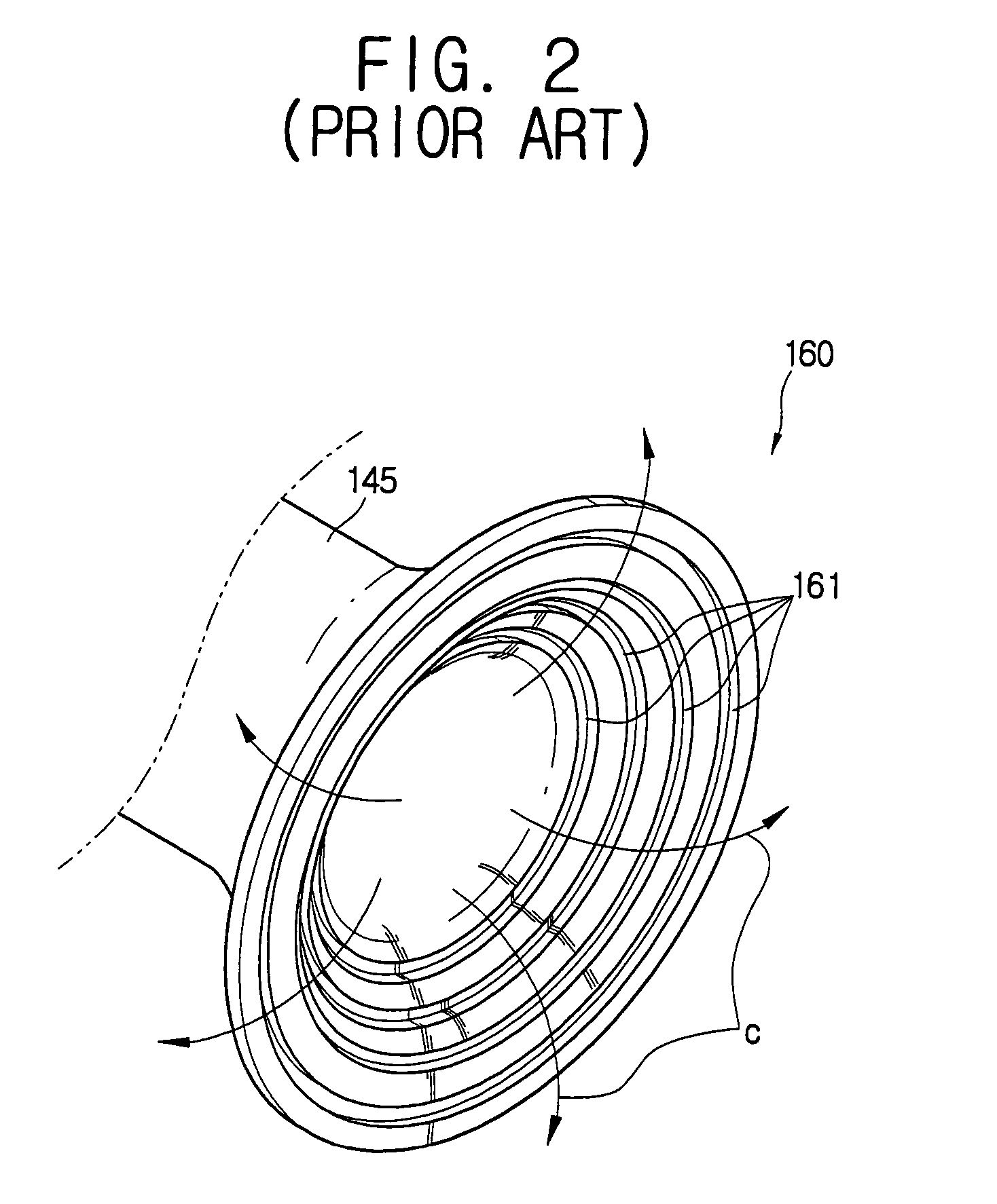
[0052]Thus, in the turbo compressor according to the present invention, the plurality of auxiliary channels 63 are additionally provided on the shroud 60, so that the backflow is eliminated even when the backflow “a” from the first diffuser to the first gas suction part 45 flows over the channels 61.

[0053]In the above descriptions, the channels 61 and the auxiliary channels 63 are applied to the first impeller 40 and the shroud 60 shrouding the first impeller 40, but it should be appreciated that the channels 61 and the auxiliary channels 63 are applied to the second impeller 50 and the shroud 60 shrouding the second impeller 50.

[0054]As described above, the present invention provides a turbo compressor in which compression efficiency is increased by eliminating a backflow and a leakage flow.


PUM


Abstract

A turbo compressor comprising a driving motor, an impeller to be rotated by the driving motor, a second gas suction part through which gas is introduced into the impeller, and a discharger through which the gas is discharged from the impeller, the turbo compressor comprises a shroud provided between the gas suction part and the gas discharger and spaced from a blade of the impeller; and a plurality of channels provided on the shroud and inclined toward the gas discharger along a rotating direction of the impeller. With this configuration, the present invention provides a turbo compressor in which compression efficiency is increased by eliminating a backflow and a leakage flow.

Description

CROSS-REFERENCE TO RELATED APPLICATIONS[0001]This application claims the benefit of Korean Patent Application No. 2004-1085, filed Jan. 8, 2004, in the Korean Intellectual Property Office, the disclosure of which is incorporated herein by reference.BACKGROUND OF THE INVENTION[0002]1. Field of the Invention[0003]The present invention relates to a turbo compressor, and more particularly, to a turbo compressor having an improved structure to eliminate a leakage flow between an impeller and a shroud.[0004]2. Description of the Related Art[0005]Generally, a turbo compressor comprises a driving motor, an impeller to be rotated by the driving motor, and a shroud spaced from a blade of the impeller. The turbo compressor sucks and compresses gas such as a refrigerant by a centrifugal force due to rotation of the impeller accommodated in the shroud.[0006]The driving motor comprises a stationary stator mounted in a motor chamber, and a rotor rotatably provided inside the stator. The rotor is i...

Claims


Application Information

Patent Timeline
Patent Type & Authority Patents(United States)
IPC IPC(8): F04D29/26F04D17/10F04D29/16F04D29/44F04D29/66
CPCF04D29/162F04D29/4206F04D29/685Y10S415/914F04D29/44
Inventor RO, SOO-HYUKKIM, CHEOL-WOO
Owner SAMSUNG ELECTRONICS CO LTD
Why Eureka
Try Eureka