Intermediate electrical connector device and its connecting structure

a technology of electrical connectors and connectors, which is applied in the direction of coupling device connections, coupling device details, printed circuits, etc., can solve the problems of reducing the precision of positioning of connections with the terminals of counter connectors, limiting the number of contacts, and unable to obtain contacts, so as to increase the number of contacts

Inactive Publication Date: 2008-03-04
HIROSE ELECTRIC GROUP
View PDF5 Cites 19 Cited by
  • Summary
  • Abstract
  • Description
  • Claims
  • Application Information

AI Technical Summary

Benefits of technology

[0015]Accordingly, it is an object of the invention to provide an intermediate electrical connector, which is improved to enable flexible floating and increase the number of contacts at the time of connecting with the counter connector to desired number, and to provide the connecting structure.
[0022]If the receiving groove is formed to have a width to keep space from the intermediate board, has a protrusion on the two facing inner surfaces such that the positions are different in the longitudinal direction of the groove, and the distance between the protrusions in the groove width direction is generally same as the thickness of the intermediate board, positioning of the intermediate board can be precisely and stably done in the thickness direction of the intermediate board by the protrusions. In addition, since the distance between the grooves can be made small, the portion between the grooves can be flexible, which enables floating of the intermediate board in the direction.
[0023]If the receiving groove is formed to have a depth that places the intermediate board including the connecting section therein, staining of the connecting section by accidentally touching by a finger or something can be prevented, so that protection effect can be obtained. By providing to the sub-member a guide frame to receive and fit the outer wall of the connecting body, the fitting to the connecting body can be made easy, and the connecting body can be fitted and held securely. In this case, if the guide frame is formed to have larger height in the fitting direction than the intermediate board, which is held by the sub-member, the space at the both sides between the intermediate board and the guide frame is too small to put a finger therein, and therefore the connecting section is protected. As for other intermediate boards, intermediate boards are protected by each other by arranging a plurality of intermediate boards with relatively small pitch.

Problems solved by technology

First, the holding body 51 is formed as one piece and has large rigidity, so that it can be hardly elastically deformed. For this reason, two intermediate boards 52 attached to the holding body have to be attached having some looseness at the catch in the thickness direction of the intermediate board, in order to enable positioning in the thickness direction, i.e. “floating”. However, since the intermediate board is positioned by the center hole and the protrusion of the joint section in order to precisely position many contacts of each intermediate board, the protrusion is tightly fitted into the hole, and floating in the thickness direction cannot be securely obtained even with looseness. On the other hand, in order to securely obtain the floating, the fitting between the hole and the protrusion has to be loosened, which destabilizes the position of the contacts between the two intermediate boards in the arranging direction, and therefore, the precision in positioning of connection with the terminal of the counter connector becomes reduced. Accordingly, in order to secure the precision in positioning, in addition to floating in the thickness direction of the intermediate board, floating in the longitudinal direction, i.e. arrangement direction of the contacts, cannot be obtained.
Second, since only two intermediate boards can be used, there is limitation in the number of contacts that can be created by the intermediate connectors. If the number of contacts is increased by the two intermediate boards, the intermediate boards have to be very long in the lateral direction, and correspondingly, the counter connector also has to be very long, which is not preferable for attaching to the circuit board of the counter connector.

Method used


Image

  • Intermediate electrical connector device and its connecting structure
  • Intermediate electrical connector device and its connecting structure
  • Intermediate electrical connector device and its connecting structure

Examples


Embodiment Construction

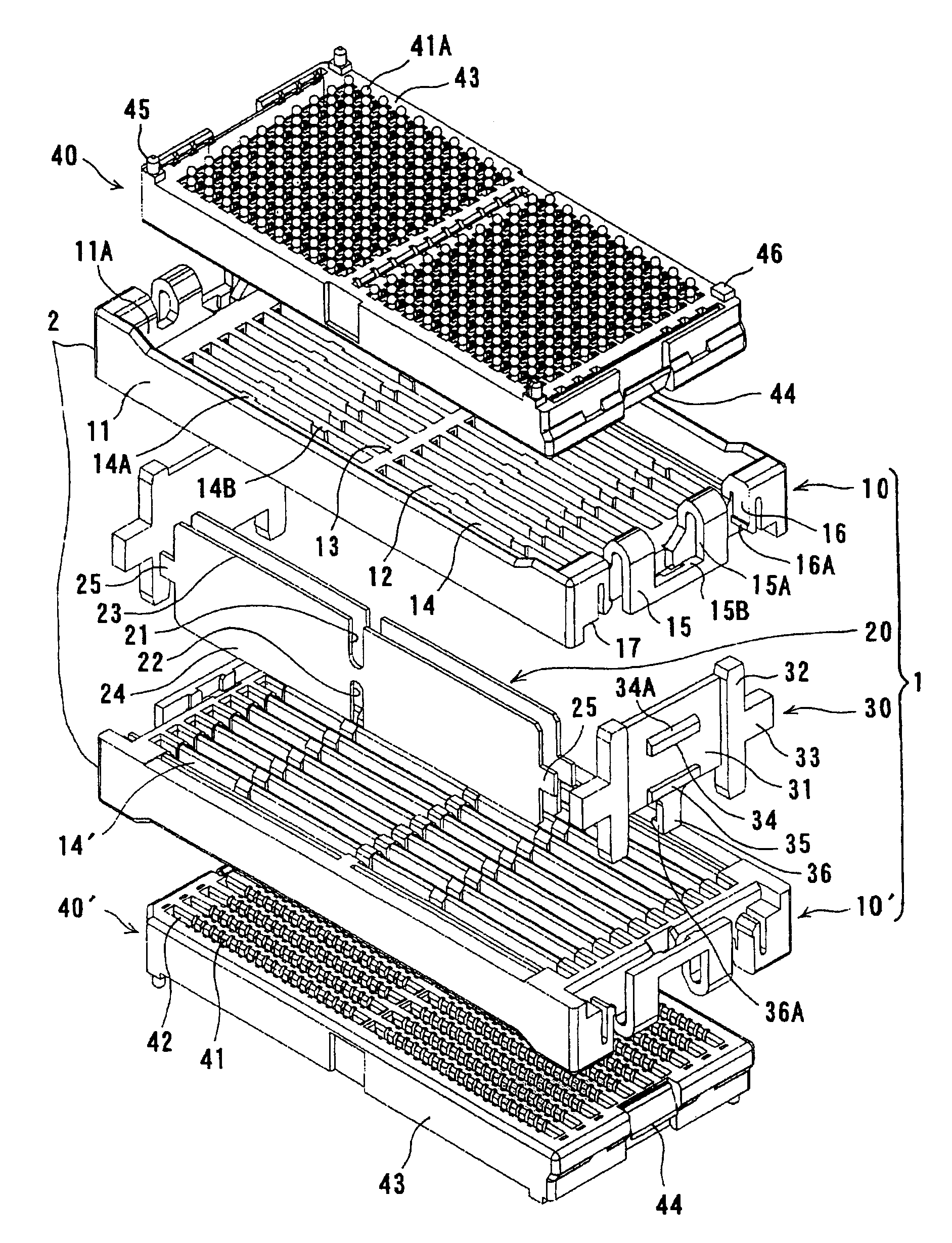
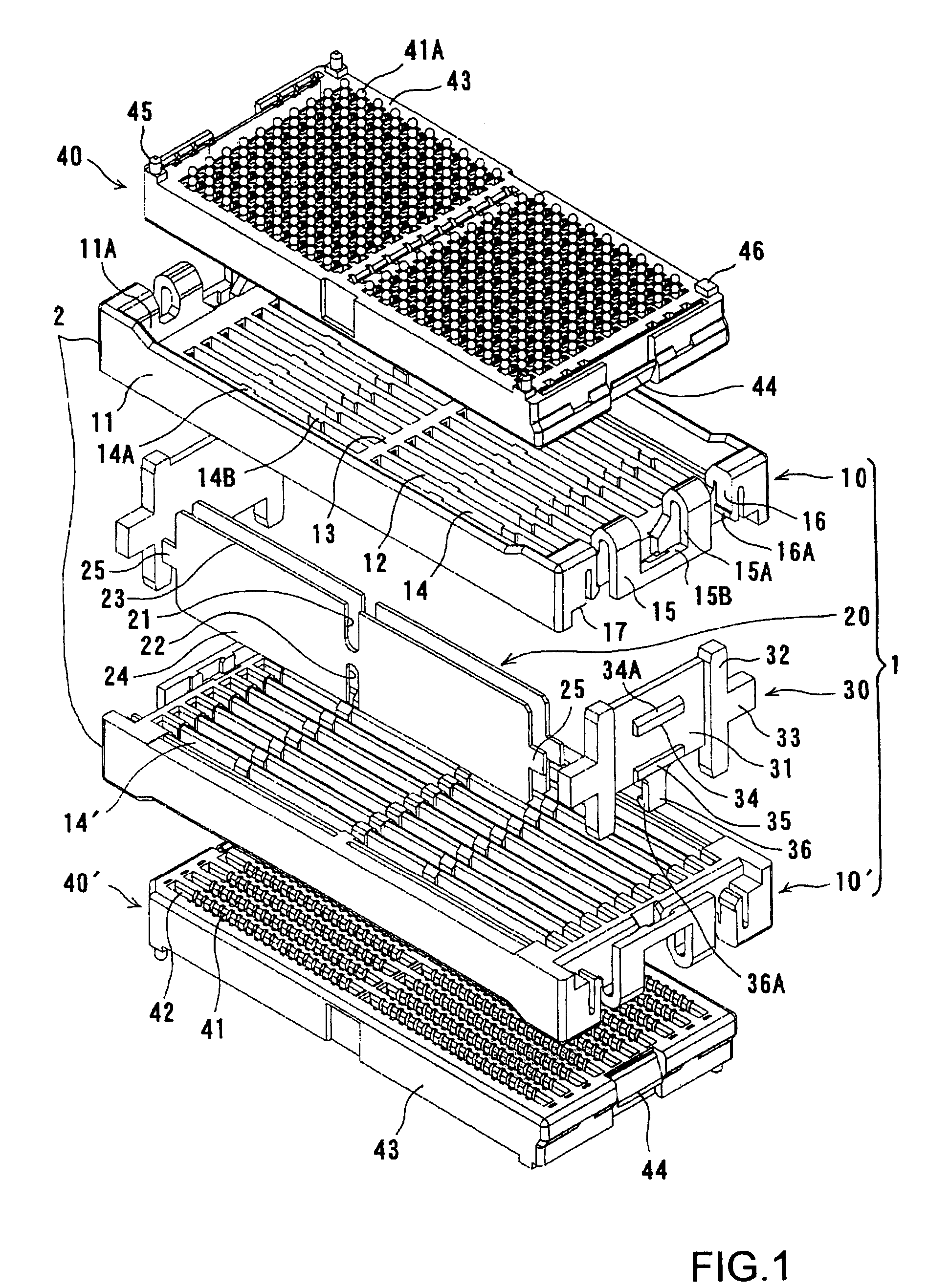
[0033]Embodiments of the invention will now be described with reference to the accompanying drawings, FIGS. 1-6. FIG. 1 illustrates an embodiment of the intermediate connector device of this invention, and also separately illustrates two connecting bodies, which are to be connected to the intermediate connector device. In FIG. 1, the two connecting bodies are illustrated as connectors as an example.

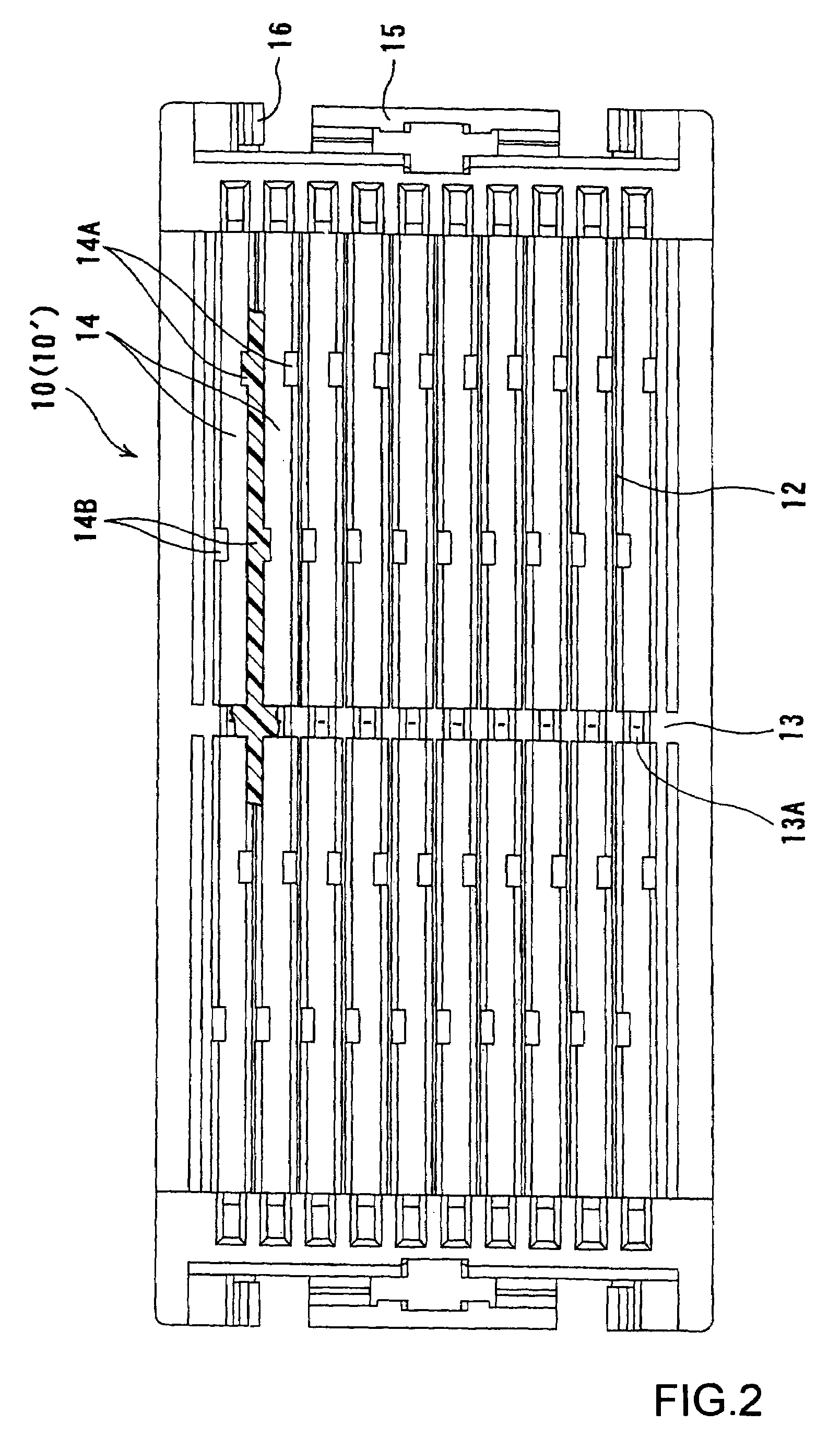
[0034]In FIG. 1, the intermediate connector device 1 of this embodiment comprises a holding body that is comprised of two sub-members 10 and 10′, an intermediate board 20 held by the sub-members, and a joint member 30 to joint the sub-members. In this embodiment, the two sub-members 10 and 10′, which are arranged above and below the intermediate connector, are identically formed, but the lower sub-member 10′ is arranged upside down with regard to the upper sub-member 10. In addition, the upper and lower counter connectors 40 and 40′, which are connecting bodies to be connected to the inte...


PUM


Abstract

An intermediate electrical connector device, which easily enables “floating”, includes an intermediate board (20) having two connecting sections (23A) and (24A), which are respectively formed at the edges (23) and (24), to connect between two connecting bodies (40) and (40′), and a holding body to hold the intermediate board between two connecting sections. The holding body is divided into a plurality of sub-members (10) and (10′) at a surface perpendicular to the fitting direction between the two connecting bodies. The intermediate board is held by one of the sub-members through at least partial fitting, and forms space from another sub-member. The sub-members can be displaced relative to each other on the surface perpendicular to the fitting direction at least one direction parallel and perpendicular to the intermediate board.

Description

BACKGROUND OF THE INVENTION[0001]1. Field of the Invention[0002]The present invention relates to an intermediate electrical connector device to electrically connect two facing connecting bodies via an intermediate board, and relates to its connecting structure.[0003]2. Description of the Related Art[0004]JP 2001-143786 discloses an intermediate connector to connect two facing connectors, which are respectively mounted onto two circuit boards, via an intermediate connector.[0005]As shown in FIG. 7, the intermediate connector 50 of this patent reference comprises a holding body 51, which is referred to as “guide frame”, and an intermediate board, which is held by the holding body 51.[0006]The holding body 51 has a columnar section 53 arranged on the right and left sides, and a flat joint section 54, which extends in the lateral direction and joint between the columnar sections 53. One of the columnar sections 53 has a catch 53A, and the other columnar section 53 has an elastic catch 5...

Claims


Application Information

Patent Timeline
Patent Type & Authority Patents(United States)
IPC IPC(8): H01R12/00H05K1/00H01R13/631H01R31/06
CPCH01R13/6315H01R12/716
Inventor TAKADA, TOSHIYUKJ
Owner HIROSE ELECTRIC GROUP
Why Eureka
Try Eureka